Copyright © Siemens AG 2016. All rights reserved
159
ERTEC 200P-2 Manual
Technical data subject to change
Version 1.0
2.3.5.2 EMC Reset and Clock
In
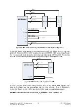
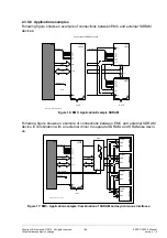
main ximum memory configuration at the EMC interface is shown (2x SDRAM devices,
2x Burst Flash devices, 1x Peripheral / Level Shifter for 3,3V). Each memory device gets
its own clock. The ERTEC 200P has 3 Clocks for the SDRAM memory
(CLK_O_SDRAM2/1/0) and 3 Clocks for the Burst Flash memory (CLK_O_BF2/1/0)
.
The CLK_O_SDRAM0 / CLK_O_BF0 must be used for feedback the external
memory clock to the ERTEC 200P inputs CLK_I_SDRAM / CLK_I_BF.
Figure 10: EMC interface with two SDRAM / two Burst Flash configuration
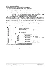
CLK_O_SDRAM1 / CLK_O_BF1 are used for the respective memory device no.1 and
CLK_O_SDRAM2 / CLK_O_BF2 for the respective memory device no.2.
Содержание ERTEC 200P
Страница 1: ...ERTEC 200P 2 Enhanced Real Time Ethernet Controller Manual ...
Страница 309: ...Copyright Siemens AG 2016 All rights reserved 309 ERTEC 200P 2 Manual Technical data subject to change Version 1 0 ...
Страница 492: ...Copyright Siemens AG 2016 All rights reserved 492 ERTEC 200P 2 Manual Technical data subject to change Version 1 0 ...

