Copyright © Siemens AG 2016. All rights reserved
465
ERTEC 200P-2 Manual
Technical data subject to change
Version
1.0
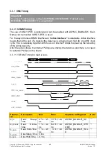
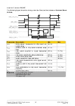
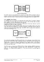
The PN-IP in ERTEC 200P outputs both the clock and the SMI interface data with the
system clock. The correct timing is ensured by the circuit – the SMI interface accepts data
with a rising clock edge and outputs data with a falling clock edge.
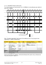
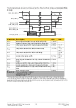
As an example of constraining for the PN-IP in the ERTEC 200P, the following values
should be used for a load of min.10pF / max. 20pF – relaxed default timing. The interface
will in fact, like the MII interface, be internal to the package (SIP); the load capacity will no
longer have a min/max value (which will also be much lower).
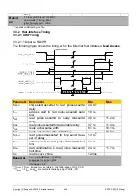
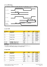
3.3.3.2.1 MDIO Timing at the Integrated PHY
Symbol
Parameter
Min.
Max.
Unit
Note
T
CO
Clock2out MDIO
4.8
21.5
ns
CLK_MDC
T
H
Hold Zeit MDIO (in)
0.0
ns
CLK_MDC
T
SU
Setup Zeit MDIO (in)
11.7
ns
CLK_MDC
Based on
3.3.3.3 Integrated PHY Timing
3.3.3.3.1 PHY FX Timing
The Ethernet interfaces of the integrated PHYs are part of the PHY macro and do not have
any constraints. The differential signals for controlling fiber-optic lines (FX interface) are
not an integral part of the PHY macro; they are connected separately. The most important
thing for these signals is as small as possible a skew between the differential pairs – there
is no other reference.
Note:
3.3.3.3.2 PHY LED Timing
These outputs of ERTEC 200P are part of the GPIOs.
3.3.3.4 PNPLL Timing
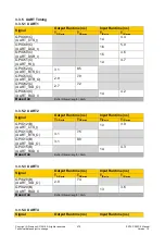
A total of 21 PN-PLL signals are sent to the ERTEC 200P top level from the PN-IP Of
these signals, the
nine
output signals PNPLL_out(8..0) can be connected to ext. pins over
GPIOs. PNPLL_Extin can also be connected as an input signal from an ext.pin to the
PNPLL over a GPIO.
One of the nine output signals PNPLL_out(8..0) can be used as SyncOut for measuring
the synchronism of individual nodes in a network topology.
This requires the following configuration in the PN-IP:
- Register
CycleCompare_A_1
= 0x0000_0000 (trigger pulse at start of cycle)
- Register
PLL_OUT_Control_0
= 0x0000_0016 (event appears at the signal
pn_pll_o(0))
Multiplexers and GPIOs must be set accordingly on the ERTEC 200P top level (see
2.3.8.1.3).
PNPLL_OUT can be measured at the selected GPIO pin; the signal is generated as fol-
lows:
Содержание ERTEC 200P
Страница 1: ...ERTEC 200P 2 Enhanced Real Time Ethernet Controller Manual ...
Страница 309: ...Copyright Siemens AG 2016 All rights reserved 309 ERTEC 200P 2 Manual Technical data subject to change Version 1 0 ...
Страница 492: ...Copyright Siemens AG 2016 All rights reserved 492 ERTEC 200P 2 Manual Technical data subject to change Version 1 0 ...


