Copyright © Siemens AG 2016. All rights reserved
36
ERTEC 200P-2 Manual
Technical data subject to change
Version 1.0
i.e. without external resistors, is a NOR flash with an access width of 32 bits and is selected with the internal pull
circuit (highlighted in
blue
).
2)
Code mode is not supported
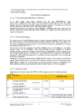
Table 3: Boot mode adjustment
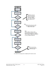
2.3.1.5.1.2 Handling after ARM926EJ-S SW Reset
If a soft reset has been carried out for the ARM926EJ-S core
(
RES_SOFT_ARM926_CORE
),
RES_STAT_REG.SW_RES_ARM926
is set in the SCRB
register and the primary boot loader is
not
processed. Instead, the program is continued
from the address in the
RES_SOFT_RETURN_ADDR
register.
Following a HW reset, i.e. power on, ASIC (XRESET), ARM926 watchdog or SW reset for
ERTEC 200P,
RES_STAT_REG.SW_RES_ARM926
is cleared and the primary boot
loader is processed.
2.3.1.5.1.3 Memory Swapping
The reset vector of the ARM926 processor points to address 0x0000_0000. That is why
the mirrored area of the boot ROM starts at address 0x0000_0000 after reset (power on,
HW, SW or ARM926 watchdog reset). The boot ROM can also be addressed in its origi-
nal address range (see 2.4.1).
At the end of the boot operation, the EMC SDRAM (max. of 64 MByte) or the EMC
memory (max. of 1x 64 MByte, chip select Bank0) can be mapped to address
0x0000_0000h to allow the exception vector table for ARM926EJ-S to be created in ad-
dress range 0x0000_0000 – 0x0000_001F. The original address ranges for boot ROM (in
segment 4), EMC SDRAM (segment 2) and EMC memory (segment 3) are not affected
by memory swapping.
Swapping is done by programming the
MEM_SWAP
register in the system control status
register block SCRB (see 2.3.10.9.22). With reserved coding, there is no swapping in the
MEM_SWAP
register (or to be precise, no memory space is shown in segment 0). If
these addresses are then accessed at the AHB, a QVZ (see 2.3.2.5.1) is triggered.
2.3.1.5.1.4 Startup Times
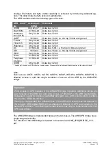
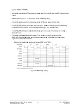
Depending on the boot mode, the ERTEC 200P requires one of the following startup
times:
Boot
mode
Booting…
t
1
t
2
(startup time)
1
External NOR flash
(16-bit),
ASYNC_
ADDR_MODE
= 1
1.5 ms
1.5 ms
Compile mode
2
External NOR flash (32-
bit),A
SYNC_
ADDR_MODE
= 1
Compile mode
1.5 ms
1.5 ms
5
SPI master (RD Cmd:
1.07 ms
5.8 ms
(256 data bytes copied)
Each additional byte requires
Содержание ERTEC 200P
Страница 1: ...ERTEC 200P 2 Enhanced Real Time Ethernet Controller Manual ...
Страница 309: ...Copyright Siemens AG 2016 All rights reserved 309 ERTEC 200P 2 Manual Technical data subject to change Version 1 0 ...
Страница 492: ...Copyright Siemens AG 2016 All rights reserved 492 ERTEC 200P 2 Manual Technical data subject to change Version 1 0 ...


