Copyright © Siemens AG 2016. All rights reserved
373
ERTEC 200P-2 Manual
Technical data subject to change
Version 1.0
2.3.10.9.16
Clear DMA Request
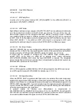
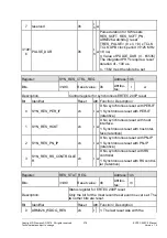
2.3.10.9.17 SPI Parity Error
A parity error at the group interrupt INT_SPI_ParityERR for the ARM-ICU (IRQ17) is
generated in SPI_PARITY_ERROR.
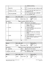
2.3.10.9.18 XHIF Mode
Eight different address ranges (pages) of the ERTEC 200P can be addressed individually
over the parallel host interface in HostIF (XHIF, see 2.3.6.2). The size of the max. ad-
dress ranges (pages) can be configured with XHIF_MODE. Following a reset, a default
max. address range per page is 1 MByte; the ASIC pin XHIF_XCS_R_A20 is connected
to XHIF_XCS_R, so the pages can be reconfigured at the XHIF interface by the ext. host.
When XHIF_MODE = '1', the ASIC pin XHIF_XCS_R_A20 is connected to XHIF_A20,
expanding the address range for access to the ERTEC 200P to 2 MByte per page.
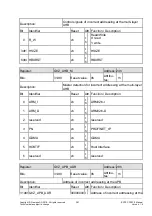
2.3.10.9.19 Ext. Driver Enable
With EXT_DRIVER_EN, you can configure the address range of the asynchronous EMC
interface (CS0…CS3) for the chip select-specific control of an external driver at the EMC
interface using the DTXR and XOE_DRIVER signals (for details, see 2.3.5.4.4).
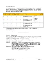
It should also be possible to configure the CS0 address range (0x3000_0000 –
0x33FF_FFFF) at the EMC pin XRDY_BF by latching driver control information
(
EXT_DRIVER_DISABLE_CS0)
when the reset (XRESET) is cleared. The integrated
pull-up means that control for an external driver is deactivated by default and needs to be
activated with a pull-down for the module.
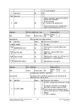
2.3.10.9.20 SPI Mode
SPI1 or SPI2 operation as MISO/MOSI or SPI-IP wiring straight to the GPIOs can be set
on an SPI-specific basis with SPI_MODE (for details, see 2.3.10.7.3)
2.3.10.9.21 SD Signal Handling
When the ERTEC 200P is operated with fiber-optics, the external fiber-optic transceiver
signals with signal detect (SD) whether a fiber-optic signal has been received. This SD
signal is to be filtered on a port-specific basis and output as a differentiated signal for the
ERTEC 200P integrated PHY. To avoid complex logic for preprocessing the SD signal in
a given module, the ERTEC 200P can implement port-specific filtering and differentiation
of the SD signal itself with SD_CONTROL.
A general enable for filtering and differentiation is implemented in
SD_CONTROL.SD1/2_ENABLE for this purpose. If it is not, the ERTEC die port-specific
SD+ and SD- are switched to high impedance to continue to allow the direct connection
of an external differentiated SD signal over the ERTEC 200P BGA balls.
Содержание ERTEC 200P
Страница 1: ...ERTEC 200P 2 Enhanced Real Time Ethernet Controller Manual ...
Страница 309: ...Copyright Siemens AG 2016 All rights reserved 309 ERTEC 200P 2 Manual Technical data subject to change Version 1 0 ...
Страница 492: ...Copyright Siemens AG 2016 All rights reserved 492 ERTEC 200P 2 Manual Technical data subject to change Version 1 0 ...


