


Copyright © Siemens AG 2016. All rights reserved
487
ERTEC 200P-2 Manual
Technical data subject to change
Version
1.0
Signal
Signal description
Dir
Function description
Ball
Used for Boundary scan test.
For normal operation this pin must be connected by a
1k Ohm Pull down resistor to GND.
P1FXEN
Port 1 Fiber Optic Enable
out
Port 1 Fiber Optic Enable
This pin is not used and should be unconnected.
The Fiber Optic transceiver should be enabled all the
time by prober pull resistor.
C9
P2FXEN
Port 2 Fiber Optic Enable
out
Port 2 Fiber Optic Enable
This pin is not used and should be unconnected.
The Fiber Optic transceiver should be enabled all the
time by prober pull resistor.
Y8
TESTDOUT5
Test Output 5
out
Test Output 5
This pin is not used and should be unconnected.
B8
TESTDOUT6
Test Output 6
out
Test Output 6
This pin is not used and should be unconnected.
A8
TESTDOUT7
Test Output 7
out
Test Output 7
This pin is not used and should be unconnected.
V10
CLK_O_SDRAM2 EMC SDRAM Clock Out
bi
Clock Output SDRAM 2
In normal operation this signal is connected to
second SDRAM, upper 16 Bit. In case where just one
SDRAM is implemented an external 10k Ohm Pull up
resistor must be connected.
H5
CLK_O_BF0
EMC Burst Flash CLK Out
bi
Clock Output Burst Mode Flash 0
In normal operation this signal is connected to
CLK_I_BF. In case where no Burst Mode Flash is
implemented an external 10k Ohm Pull up resistor
must be connected.
M5
CLK_O_BF1
EMC Burst Flash CLK Out
bi
Clock Output Burst Mode Flash 1
In normal operation this signal is connected to first
Burst Mode Flash, lower 16 Bit . In case where no
Burst Mode Flash is implemented an external 10k
Ohm Pull up resistor must be connected.
N5
CLK_O_BF2
EMC Burst Flash CLK Out
bi
Clock Output Burst Mode Flash 2
In normal operation this signal is connected to
second Burst Mode Flash, upper 16 Bit . In case
where just one Burst Mode Flash is implemented an
external 10k Ohm Pull up resistor must be connect-
ed.
M6
CLK_I_BF
EMC Burst Flash CLK In
in
Clock Input
Burst Mode Flash
In normal operation this signal is connected to
CLK_O_BF0 . In case where no Burst Mode Flash is
implemented an external 10k Ohm Pull up resistor
must be connected.
L5
NC
Reserved
in Reserved
This pin is not used and must be connected by a 1k
Ohm Pull up resistor to VDD33.
P6
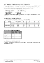
Figure 58: Recommendation for handling special function signals
Содержание ERTEC 200P
Страница 1: ...ERTEC 200P 2 Enhanced Real Time Ethernet Controller Manual ...
Страница 309: ...Copyright Siemens AG 2016 All rights reserved 309 ERTEC 200P 2 Manual Technical data subject to change Version 1 0 ...
Страница 492: ...Copyright Siemens AG 2016 All rights reserved 492 ERTEC 200P 2 Manual Technical data subject to change Version 1 0 ...