Copyright © Siemens AG 2016. All rights reserved
277
ERTEC 200P-2 Manual
Technical data subject to change
Version 1.0
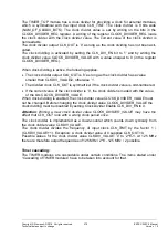
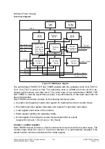
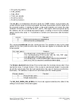
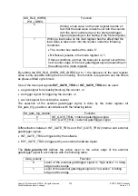
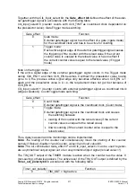
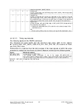
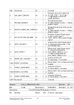
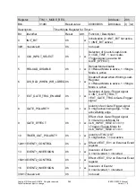
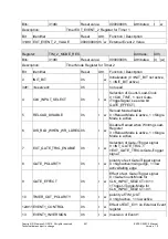
Together with the Clk_input_select bit, the
Gate_effect bit
defines the effect of the exter-
nal gate/trigger signal in accordance with the following table:
Clk_input_select=0 (counter counts with CLK_TIMT as count/load clock dependemt on
the preselector value): Gate/Trigger mode switching:
Gate_effect
Function
0
Gate mode:
External gate/trigger signal has the effect of a gate (=gate mode)
for the count/load clock and has to be active for counting
1
Trigger mode:
Each active signal edge of the external gate/trigger signal causes
the triggering of the counter with the reload value if the current
counter value is unequal to the reload value or has no effect if
the current counter value is equal to the reload value (=Trigger
mode)
Note on the trigger mode:
If the active signal edge of the external gate/trigger signal occurs in the Trigger mode
during CLK_EN=1 and then CLK_EN becomes 0 without the preselector value having
gone to 0, the previous active signal edge only becomes effective when CLK_EN is 1
again and the preselector value is 0, i.e. the requirement does not get lost because of
CLK_EN=0.
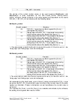
Clk_input_select=1 (counter counts with external gate/trigger signal as count/load clock
(edge evaluation)): Count/Toggle mode switching:
Gate_effect
Function
0
Count mode:
External gate/trigger signal is the count/load clock (Count mode)
1
Toggle mode:
External gate/trigger signal is the count/load clock and causes
the switching between
loading of the counter with the reload value (if the current
counter value is unequal to the reload value)
down-counting (if the current counter value is equal to the
reload value)
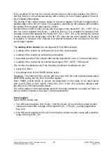
Thus, delays as well as time monitorings can be implemented.
Note: The loading of the counter can simultaneously mean the starting of the counter,
namely if Reload_disable=1 and Counter_value=0 and load value #0.
Note: The bit combination Gate_effect=1 and Clk_input_select=1 can be used to gener-
ate a symmetrical output signal out of an unsymmetrical input signal (reload value=1).
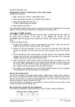
The TIM_OUT output of the TIMER module is active when the counter has the value ’0’
(non-saving), otherwise passive. The active level of the TIM_OUT output is defined by the
Timer_out_polarity bit
in accordance with the following table:
Timer_out_polarity
Function
0
TIM_OUT = high active
Содержание ERTEC 200P
Страница 1: ...ERTEC 200P 2 Enhanced Real Time Ethernet Controller Manual ...
Страница 309: ...Copyright Siemens AG 2016 All rights reserved 309 ERTEC 200P 2 Manual Technical data subject to change Version 1 0 ...
Страница 492: ...Copyright Siemens AG 2016 All rights reserved 492 ERTEC 200P 2 Manual Technical data subject to change Version 1 0 ...


