Copyright © Siemens AG 2016. All rights reserved
335
ERTEC 200P-2 Manual
Technical data subject to change
Version 1.0
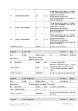
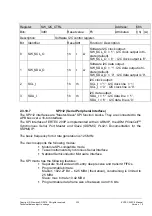
Register:
SW_I2C_CTRL
Address:
68h
Bits:
3dt0
Reset
value:
Fh
Attributes:
r(h) (w)
Description:
Software I2C control register.
Bit Identifier
Reset Attr.
Function / Description
0
SW_SCL_O
1h r w
Software I2C clock output:
SW_SCL_O = '1' : I2C clock output is tri-
state (default).
SW_SCL_O = '0' : I2C clock output is '0'.
1
SW_SDA_O
1h r w
Software I2C data output:
SW_SDA_O = '1' : I2C data output is tri-
state (default).
SW_SDA_O = '0' : I2C data output is '0'.
2
SCL_I
1h rh
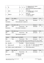
I2C clock output:
SCL_I = '1' : I2C clock line = '1'.
SCL_I = '0' : I2C clock line is '0'.
3
SDA_I
1h rh
I2C data output:
SDA_I = '1' : I2C data line = '1'.
SDA_I = '0' : I2C data line is '0'.
2.3.10.7
SPI1/2 (Serial Peripheral Interface)
The SPI1/2 interfaces are "Master-Slave" SPI function blocks. They are connected to the
APB bus over a 16-bit interface.
The SPI interface of ERTEC 200P is implemented with an ARM IP, the
ARM PrimeCell
TM
Synchronous Serial Port Master and Slave (SSPMS) PL021
. Documentation for the
SSPMS IP:
The basic frequency for bit rate generation is 125 MHz.
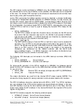
The macro supports the following modes:
Motorola SPI-compatible mode
Texas Instruments Synchronous Serial Interface
National Semiconductor Microwire Interface
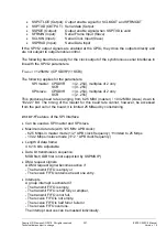
The SPI macro has the following features:
Separate 16-bit wide and 8-entry deep receive and transmit FIFOs
Programmable bit rate:
Master: 1922.27 Bd – 62.5 MBd (theoretical), constraining is limited to
25 MBd
Slave: max. bit rate 10.42 MBd
Programmable data frame size of between 4 and 16 bits
Содержание ERTEC 200P
Страница 1: ...ERTEC 200P 2 Enhanced Real Time Ethernet Controller Manual ...
Страница 309: ...Copyright Siemens AG 2016 All rights reserved 309 ERTEC 200P 2 Manual Technical data subject to change Version 1 0 ...
Страница 492: ...Copyright Siemens AG 2016 All rights reserved 492 ERTEC 200P 2 Manual Technical data subject to change Version 1 0 ...


