Copyright © Siemens AG 2016. All rights reserved
37
ERTEC 200P-2 Manual
Technical data subject to change
Version 1.0
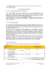
0xE8)
14.7 us
6
SPI master (RD Cmd:
0x03)
1.07 ms
5.8 ms
(256 data bytes copied)
Each additional byte requires
14.7 us
7
XHIF (external host)
1.06 ms
Depends on
-
access time for the external
master
-
the configuration of the XHIF
-
the destination address (typ.
ARM926 TCM)
t
1
: Time between XRESET end and the first data being loaded to the 2nd boot loader.
Note: This time includes the setup time of 1235.5µs (see 4.8.5) and, depending on the
boot, if applicable also the required setup times for the memory.
t
2
: Time until the first command of the 2nd boot loader is executed (startup time). This
includes the time for
copying data. If the alternative block is used or several
data bytes are copied, the time may be longer.
The startup times in ERTEC 200P are therefore calculated on the basis of:
t
2
Table 4: Startup Times
2.3.1.5.2
Boot mode 1 … 2 (booting with NOR flash) in compile mode
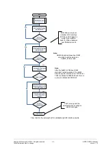
When you boot from the external NOR flash in compile mode, you can choose between
16-bit and 32-bit ROM. Booting is with EMC Peripheral Bank 0 (XCS_PER0)
After reset, the ARM926 starts the instruction fetches from the primary boot loader in the
boot ROM that is shown at address 0x0. The EMC interface (memory bank signal CS0) is
set to slow timing by the primary boot loader. The bus width is selected using the boot
pins, which are evaluated by the boot software and which configure the relevant periph-
eral bank.
The next boot code command (secondary boot loader) is processed from the NOR flash.
This requires a jump to 0x3000_0000 (NOR flash memory address: 0x0000_0000).
If the user program is to be processed straight from the NOR flash, the ARM926
interrupt vector table must be stored from NOR flash memory address
0x0000_0000 (see 2.3.1.5.1). The secondary boot loader must implement re-
mapping (
MEM_SWAP.SWAP
= "10", see 2.3.10.9.7) to show the vector list in the
NOR flash at address 0x0000_0000.
If the user program is to be processed from the TCM (I-TCM) or SDRAM, the sec-
ondary boot loader must copy the data from NOR flash address 0x0000_0000 to
the required destination memory (D-TCM, SDRAM), configure the relevant D-TCM
as I-TCM (
TCM926_MAP
, see 2.3.10.9.14) or remap the SDRAM to address
0x0000_0000 (
MEM_SWAP.SWAP
= "01", see 2.3.10.9.7).
The complete interrupt vector table is available in the boot ROM to prevent system dead-
lock. When an interrupt or an exception occurs, a restart is always carried out if the vector
Содержание ERTEC 200P
Страница 1: ...ERTEC 200P 2 Enhanced Real Time Ethernet Controller Manual ...
Страница 309: ...Copyright Siemens AG 2016 All rights reserved 309 ERTEC 200P 2 Manual Technical data subject to change Version 1 0 ...
Страница 492: ...Copyright Siemens AG 2016 All rights reserved 492 ERTEC 200P 2 Manual Technical data subject to change Version 1 0 ...


