Copyright © Siemens AG 2016. All rights reserved
121
ERTEC 200P-2 Manual
Technical data subject to change
Version 1.0
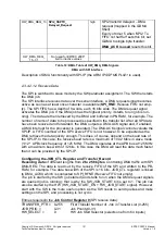
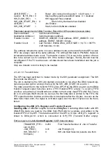
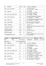
HW_DMA_REQ_13
SPI2_SSPTX_
Delayed_Request
high
SPI2 transmit delayed – DMA
request (mapped in the GDMA
Shell)
Expiry of timer 5 when 'SPI2 Tx-
FIFO not half full' sets this bit; set
GDMA to single byte transfer.
DMA_ACK is used
resets this bit.
HW_DMA_REQ_
15...31
Not used for ERTEC 200P;
tied to inactive values
Table 12: DMA, Table of HW_DMA_REQ-Signals
DMA with SPI Interface
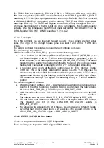
Description of DMA functionality with SPI-IP (the ARM IP
SSPMS PL021
is used).
2.3.4.2.1.2 Receive Data
The SPI is switched to slave mode by the SW parameter assignment. The SW then starts
the DMA job.
The SPI interface receives data over the serial interface. A DMA request signal becomes
active as soon as at least once character is available (
SPI_RNE
: Receive FIFO not emp-
ty). The SPI FIFO has a depth of 8 words, each 16 bits wide. The DMA request signal
activates the DMA job. If the DMA job has the highest priority, it starts to run (job is run-
ning). The data are then retrieved by the DMA and buffered in PN RAM, for example. The
number of items of data to be processed is specified in the transfer list. After all SPI data
have been received and forwarded, the DMA outputs a DMA-ACK signal and, if enabled,
a DMA interrupt for the processor is generated. The DMA-ACK signal cannot evaluate the
SPI-IP. A FIFO overflow of the SPI receive FIFO is not, however, to be expected as the
DMA retrieve the data quickly enough. This does, of course, depend on the baud rate of
the SPI-IP. In this case, the receive baud rate is a maximum of 10.42 Mb/s in slave mode
(1/12 * APB clock frequency of 125 MHz). The DMA operates at the APB bus at 125 MHz
with a maximum bus width of 32 bits. In this case, the DMA will read the data much faster
than it can be provided by the SPI-IP.
Configuring the JOB_CTL Register and Transfer_Record
Receiving data
of different lengths from
2 to 256 bytes
. Controlling DMA traffic with SPI
DMA-REQ. The data is read out by the receive FIFO of the SPI and written to the PB-
RAM, for example. The data bus width of the SPI is 16 bits. JOB_CTL register0 is linked
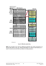
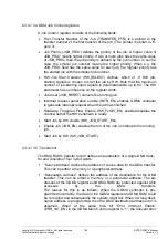
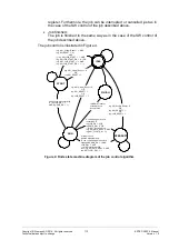
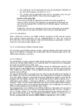
to DMA_ACK0, which is connected to SPI_RFNE (Receive FIFO not empty).
The job is started by the SW (job started) and starts to run when the DMA request signals
are queried (job is running); that is why the SW_JOB_START bit is set to 1. The job can
also be started by the HW (HW_JOB_ST HW_JOB_START signal). However,
start with the SW is the more useful option as the SW needs to send queries and make
settings on the SPI, and processing is not cyclic.
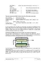
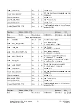
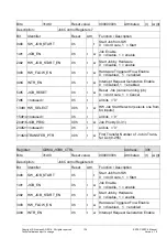
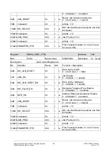
Entries requiredin the
Job Control Register 0
(SPI receive data):
TRANSFER_PTR = 0-255
First Transfer Number of Job in Transfer List (0-255)
JOB_PRIO =
0-31
Job Priority(0-31)
HW_SELECT =
0
HW Job Start Selector (selects one from 64 inputs)
Содержание ERTEC 200P
Страница 1: ...ERTEC 200P 2 Enhanced Real Time Ethernet Controller Manual ...
Страница 309: ...Copyright Siemens AG 2016 All rights reserved 309 ERTEC 200P 2 Manual Technical data subject to change Version 1 0 ...
Страница 492: ...Copyright Siemens AG 2016 All rights reserved 492 ERTEC 200P 2 Manual Technical data subject to change Version 1 0 ...

