Copyright © Siemens AG 2016. All rights reserved
261
ERTEC 200P-2 Manual
Technical data subject to change
Version 1.0
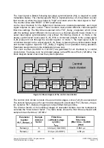
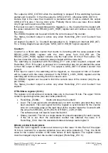
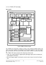
The output is XWD_OUT0=0 when the watchdog is stopped. If the watchdog has been
started and Counter0 0, then the output is XWD_OUT0=1, otherwise XWD_OUT0=0.
Denote that in the case that Counter0 is preloaded with 0 and is started, the output
XWD_OUT0 is also 1 for one clock cycle. Probably this is not a use case, this is stated
only to get a whole picture of the circuit.
If the input is Load=1, the watchdog will be triggered, i.e. the Counter0 will be loaded with
the value contained in the RELD0(_LOW/_HIGH) register and will continue counting from
this value.
The WDOG0 register can be used to fetch the current value of the counter.
The Status_Counter0 output is active only when Run/xStop_Z0=1 and Counter0 has
expired.
An expired Counter0, i.e. Counter0 decremented to 0, initiates an interrupt (WD_INT).
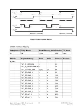
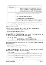
For a Timing Diagram see also figure “XWD_OUT0/ WD_INT signal sequence”
Counter1:
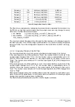
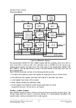
Counter1 is a 36-bit wide counter that counts to 0 starting with the value passed in the
RELD1(_LOW/_HIGH) register with the clock pulse from CLK_WD pin. The
RELD1(_LOW/_HIGH) register contains only the high order 32 bits of the counter. The
four low order bits of the counter are always loaded with the value 0x0.
The watchdog is (re)started with Run/xStop_Z1=1 and, when required, stopped with
Run/xStop_Z1=0. If Counter1 is stopped or it is started but has not yet attained the value
0, then the output is XWD_OUT1=1. The output is XWD_OUT1=0 when Counter1 has
expired.
If the input is Load=1, the watchdog will be triggered, i.e. the upper 32 bits of Counter1
will be loaded with the value contained in the RELD1(_LOW/_HIGH) register and the
watchdog will continue counting from this value to zero.
The WDOG1 register can be used to fetch the current value of the counter (only the up-
per 32 bits).
The Status_Counter1 output is active only when Run/xStop_Z1=1 and Counter1 has
expired.
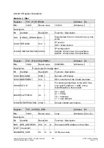
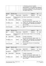
CTRL/Status register (X=0,1):
The register is 32-bit wide and contains data only in the lower 16 bits. The upper 16 bits
contain a special signature (see also 'write protection').
Run/xStop_ZX-Bits:
Starts and stops the Counter0.
Load: The Load signal acts simultaneously on both counters (provided they have
been enabled). The Load signal from the register is synchronized for the counter
side. An increasing edge at the load input of the counter loads the CounterX with
the value from RELD0(_LOW/_HIGH) or RELD1(_LOW/_HIGH).
The software does not need to reset the load bit.
Status_counterX: This bit is a single status bit present separately for each counter.
If the bit is set, then the associated counter has attained the value 0. If
Run/xStop_ZX=0, then the associated status bit always reads logical 0.
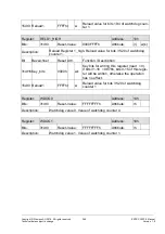
RELD0_LOW & RELD0_HIGH:
These two 32-bit registers contain user data only in the lower 16 bits. Each of the upper
16 bits is reserved for a special signature (see also 'write protection'). Thus, the 32-bit
value for the counter consists of the lower halves of both registers. The register values
must be changed only when the counter is stopped (Run/xStop_ZX = 0).
Содержание ERTEC 200P
Страница 1: ...ERTEC 200P 2 Enhanced Real Time Ethernet Controller Manual ...
Страница 309: ...Copyright Siemens AG 2016 All rights reserved 309 ERTEC 200P 2 Manual Technical data subject to change Version 1 0 ...
Страница 492: ...Copyright Siemens AG 2016 All rights reserved 492 ERTEC 200P 2 Manual Technical data subject to change Version 1 0 ...


