Copyright © Siemens AG 2016. All rights reserved
34
ERTEC 200P-2 Manual
Technical data subject to change
Version 1.0
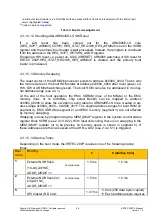
To provide the routines of the primary boot loader to the secondary boot loader, the pri-
mary boot code is located in the original address range of the boot ROM (address
0x4000_8000). The primary boot loader immediately branches from the mirrored area
(address 0x0000_0000) to its original address range (address 0x4000_8000), where it
processes the 1st-level boot code.
All boot modes with the exception of the boot mode from the external NOR flash in com-
pile mode (see 2.3.1.5.2) process the secondary boot loader stored in the TCM. As no
instructions can be processed from the D-TCM, the primary boot loader must map the
data copied to D-TCM block 3 to I-TCM block 0.
2.3.1.5.1 Primary Boot Loader
The primary boot loader is a separate memory block (boot ROM, 8 KByte) which starts
after a PowerOn reset from address 0x0. Depending on the boot mode settings (with boot
pins or in the SCRB register
BOOT_REG
, see 2.3.10.9.2), the system recognizes the
medium from which the software is to be loaded. The required system settings are only
set for the download medium and the program code (secondary boot loader) is loaded to
TCM. Finally the loaded code will be executed.
The following settings are
always
made by the primary boot loader irrespective of the
boot mode:
ASYNC_ADDR_MODE: (see /36/, page 105, register: EXTENDED_CONFIG)
-
When
ASYNC_ADDR_MODE
= '0':
no
address shift (ERTEC 200 compatible)
MA(23:0) = HADDR(23:0).
-
When
ASYNC_ADDR_MODE
= '1':
address shift depending on configured memory data width
data width = 8 bit: MA(23:0) = HADDR(23:0)
data width = 16 bit: MA(23:0) = HADDR(24:1)
data width = 32 bit: MA(23:0) = HADDR(25:2)
The bit is set in the
EXTENDED_CONFIG
register of the EMC. An entry in the
SCRB is therefore no longer required. After reset, the register bit is set to 0, i.e.
there is no address shift. In ERTEC 200P, the bit
EXTENDED_CONFIG.ASYNC_ADDR_MODE
(EMC register) is set to 1 by the
primary boot loader as the function
ASYNC_ADDR_MOD
= 0 is not likely to be re-
quired. This bit can, however, be changed by the software at any time.
Other EMC or SPI settings required are made in line with the boot mode by the primary
boot loader and in line with XHIF by the host.
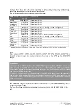
The following aspect is specific to ARM9 processors for data storage from address
0x00...00 (interrupt vector table).
Address
Data item
Comment
Priority
0x00
Reset vector Jump command following power on/WD/SW reset
Stack pointer from address:
0x0800_FD00
1 (highest)
0x04
Undefined
Instruction
Jump command after execution of an illegal opcode
Stack pointer from address:
0x0800_FC00
6 (lowest)
0x08
Software
interrupt
Jump command after SWI triggered
Stack pointer from address:
0x0800_FA00
6 (lowest)
0x0c
Opcode from
illegal ad-
Jump command after illegal opcode address is read
Stack pointer from address:
0x0800_FB00
5
Содержание ERTEC 200P
Страница 1: ...ERTEC 200P 2 Enhanced Real Time Ethernet Controller Manual ...
Страница 309: ...Copyright Siemens AG 2016 All rights reserved 309 ERTEC 200P 2 Manual Technical data subject to change Version 1 0 ...
Страница 492: ...Copyright Siemens AG 2016 All rights reserved 492 ERTEC 200P 2 Manual Technical data subject to change Version 1 0 ...


