Copyright © Siemens AG 2016. All rights reserved
342
ERTEC 200P-2 Manual
Technical data subject to change
Version 1.0
ceive overrun interrupt can be enabled and disabled with the RORIE bit in the SSPCR1
register.)
If data have been transferred from the SPI master to the SPI slave without the receive
FIFO of the master being emptied, please note: before a data transfer in the opposite
direction, i.e. from the slave to the master, the data from the previous transfer must be
cleared from the receive FIFO of the master before the slave can read the "new" data
from the receive FIFO of the master.
No new data received will be entered in the receive FIFO if it is full, but data transfer will
not automatically be cancelled.
2.3.10.7.4 Send Support with Pause between Individual Characters
In one use case, the SPI transmitters are to transmit blocks of 64 bytes, for example, in a
GDMA-compatible process. A set pause (e.g. 200 s) must however be maintained be-
tween the individual bytes. To ensure this pause, the two GDMA channels required (1
channel for SPI-TxD and 1 channel for SPI-RxD) are controlled by 2 timers.
A transfer record must be entered in the GDMA job list for each byte transfer (total: 64 + 1
transfer entries, see below). Timer 4 (SPI1) and timer 5 (SPI2) are also configured for
cyclic, SW-triggered operation with an 1-active timer output signal. A 0 run for a given
timer switches the timer output to 1 for one clock cycle in line with the TX-FIFO status
(see below) and sets the corresponding 'SPI1/2_SSPTX_Delayed_ Request' FF (located
in the GDMA shell). The GDMA controller then runs a single-byte transfer (transfer rec-
ord), generates GDMA acknowledge and resets the 'SPI1/2_SSPTX_Delayed_Request'
FF (see 0).
Flow control for generating the timer-triggered GDMA requests can only prevent an SPI
TX-FIFO overrun if the SPI TX interrupt status (TX-FIFO half full status, >= 4 bytes) is
also evaluated. A TX-FIFO overrun is possible if too short a timer cycle time is configured
with a short SPI TX transfer rate. The TX interrupt must therefore be enabled during con-
figuration of the SPI-IP (-> SSPCR1 Register(Bit 1), TIE = 1). This ensures that no char-
acters are lost; certain timer trigger pulses are, if necessary, temporarily ignored.
To ensure equidistance when the above 64-byte transfer is repeated, the timer must be
stopped after the 64th single transfer. This function is executed by the GDMA controller
as the 65th transfer entry (-> Write access to TIMER_TRIG_CONTROL_REG register ->
tim_4_clk_en or tim_5_clk_en bit reset) once the 64th single transfer is complete.
Timers 4 and 5 are also used for other functions and the timer output signals
'SPI1/2_SSPTX_Delayed_Request' can therefore also set FFs. The FFs must be specifi-
cally reset by the SW. This is done using the 'CLEAR_
SPI1/2_SSPTX_Delayed_Request' bits in the 'CLEAR_DMA_SPI_REQ_REG' SCRB
register (see 2.3.10.9.22). These register bits are not retentive; they simply activate a
reset pulse when 1 is written. There is no reset when a 0 is written, so the
'SPI1/2_SSPTX_Delayed_ Request' FFs can be operated separately.
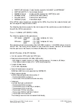
Sequence for above scenario:
1) Write GDMA job list to GDMA job list RAM (e.g. 64 single transfers plus timer stop
register access)
2) Stop timer in progress and then reset 'SPI1/2_SSPTX_Delayed_Request' FFs with
write access to 'CLEAR_DMA_SPI_REQ_REG' (SCRB)
3) Enter pause + byte transfer time as load value in timer 4 or timer 5 LOAD register
4) Configure timer mode register for SW-triggered, cyclic operation (internal gating)
Содержание ERTEC 200P
Страница 1: ...ERTEC 200P 2 Enhanced Real Time Ethernet Controller Manual ...
Страница 309: ...Copyright Siemens AG 2016 All rights reserved 309 ERTEC 200P 2 Manual Technical data subject to change Version 1 0 ...
Страница 492: ...Copyright Siemens AG 2016 All rights reserved 492 ERTEC 200P 2 Manual Technical data subject to change Version 1 0 ...


