Copyright © Siemens AG 2016. All rights reserved
237
ERTEC 200P-2 Manual
Technical data subject to change
Version
1.0
2.3.9.2.1 PLL Clock Generation
As shown in Table 16, ERTEC 200P largely runs with a synchronous 125 MHz or 250 MHz
clock. These clocks are generated with an integrated PLL. The PLL is supplied with a 25
MHz clock signal. The PLL clock source is an integrated quartz oscillator, to which an
external 25 MHz quartz must be connected (CLKP_A/B). Alternatively, an external 25 MHz
generator can be connected to the CLKP_A pin.
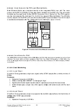
The external quartz wiring is shown in
26 (the capacity and resistor values given
here are valid for the TSX-3225 quartz types from Epson):
Figure 26: Quartz wiring
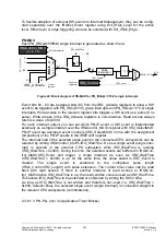
The PLL provides 500 MHz at its output. In clock generation downstream from the PLL,
the PLL output frequency is converted into:
125 MHz
System clock (CLK_SYS)
250 MHz
Synchronization in the PN-IP (CLK_TIME)
125/250 MHz
ARM926 (CLK_ARM_SLOW/FAST)
It is also possible to bypass the PLL with the configuration pin CONFIG(2) (see
2.3.10.9.3). In this case, clock supply is over the BYP_CLK pin. With a recommended
input frequency of 125 MHz, the output clocks are 125 MHz for ARM926EJ-S, system
clock and synchronization. This PLL bypass is only useful for debug operation.
Содержание ERTEC 200P
Страница 1: ...ERTEC 200P 2 Enhanced Real Time Ethernet Controller Manual ...
Страница 309: ...Copyright Siemens AG 2016 All rights reserved 309 ERTEC 200P 2 Manual Technical data subject to change Version 1 0 ...
Страница 492: ...Copyright Siemens AG 2016 All rights reserved 492 ERTEC 200P 2 Manual Technical data subject to change Version 1 0 ...


