Copyright © Siemens AG 2016. All rights reserved
264
ERTEC 200P-2 Manual
Technical data subject to change
Version 1.0
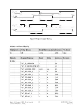
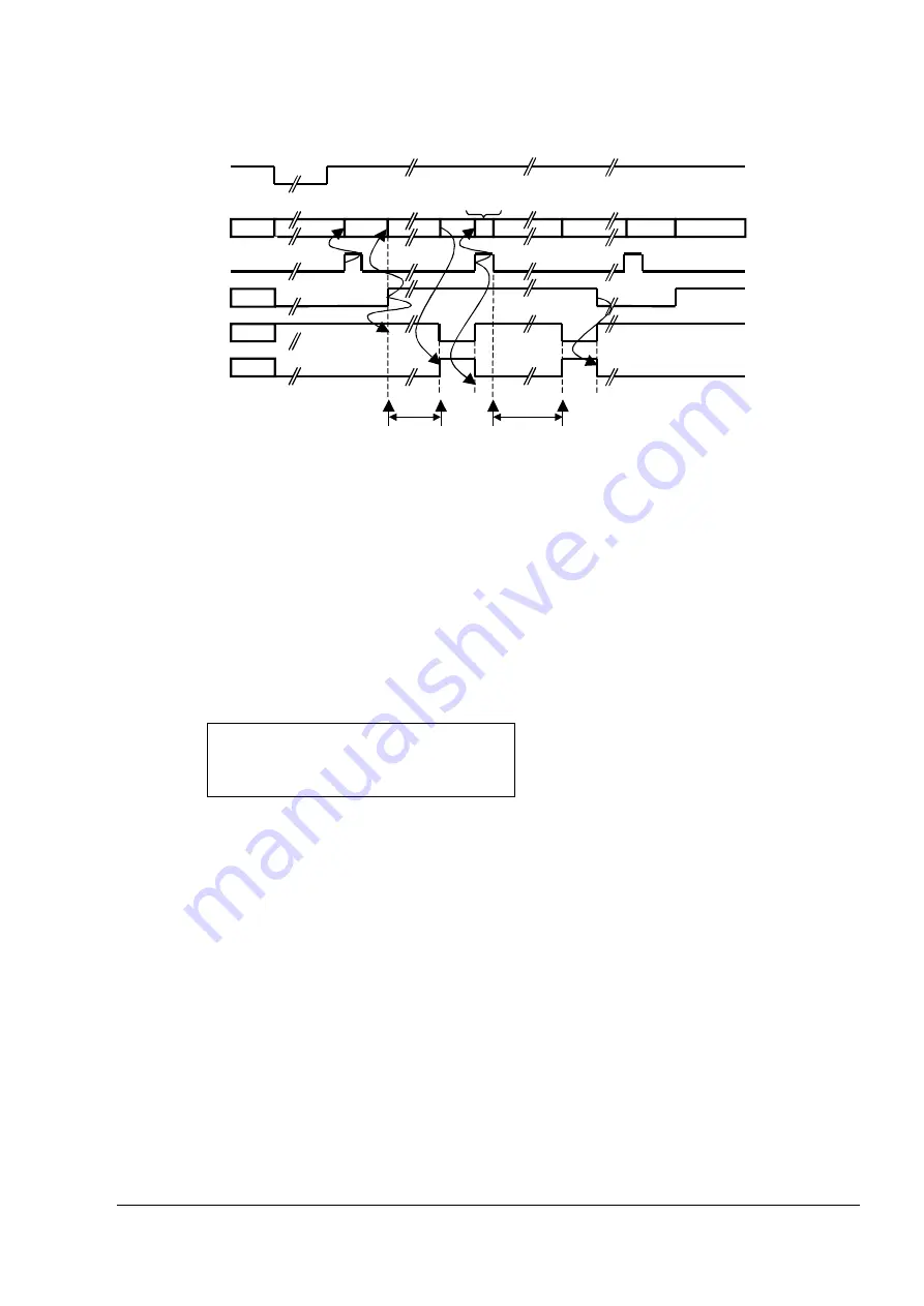
Figure 36: XWD_OUT1 signal sequence
After a reset, the XWD_OUT1 output is initially logical 1. The XWD_OUT1 output be-
comes logical 0 and the "Status_Counter1" status bit is set only after Counter1 has been
started (Run/xStop_Z1=1) and the time t2 has expired after the start or the last retrigger
pulse (Load=1).
A retrigger pulse (Load=1 & Reload-value 0) or stopping the counter (Run/xStop_Z1=0)
causes the status bit and the XWD_OUT1 output to be reset again.
IN
CLK
REF
T
RELD
t
_
_
2
)
1
16
1
(
t
2
:
Time until the counter expires
RELD1
:
Decimal value of the reload value for Counter1
T
REF_CLK_IN
: Period duration of the system cycle clock (8 ns)
T
REF_CLK_IN
= 125 MHz:
t
2MIN
= 0 sec,
t
2MAX
= 549.76 sec, Interval = 128 ns
2.3.10.2.4
Write protection of the watchdog register
If the Watchdog Control/Status register or one of the Watchdog Reload registers is to be
written, a defined bit combination in the upper 16 bits (key bits) must be written simulta-
neously. The key bits are 9876h (arbitrary). The read access returns the value 0000h in
the upper 16 bits.
2.3.10.2.5
Starting the Watchdog
The following sequence describes the initialization phase which at first has to be per-
formed by software:
Содержание ERTEC 200P
Страница 1: ...ERTEC 200P 2 Enhanced Real Time Ethernet Controller Manual ...
Страница 309: ...Copyright Siemens AG 2016 All rights reserved 309 ERTEC 200P 2 Manual Technical data subject to change Version 1 0 ...
Страница 492: ...Copyright Siemens AG 2016 All rights reserved 492 ERTEC 200P 2 Manual Technical data subject to change Version 1 0 ...

