Copyright © Siemens AG 2016. All rights reserved
269
ERTEC 200P-2 Manual
Technical data subject to change
Version 1.0
2.3.10.3
*Timer 0 – 5
2.3.10.3.1 Overview
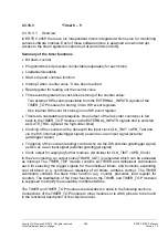
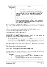
In ERTEC 200P there are six independent timers integrated which serve for monitoring
various software routines. Each of these software timers is assigned an own interrupt.
Access to the timer registers is carried out at word limits (32 bits).
Summary of the timer functions
Bit down-counter
Programmable bit prescaler connectable (separately for each timer)
Loadable/reloadable
Start, stop and continue function
Interrupt when counter value '0’ has been reached
Read register for reading out the counter value
Three event registers for event-driven storing of the counter value:
-
Two external HW events (selectable from the EXTERNAL_INPUTS signals of the
TIMER_TOP module) for storing in two HW event registers
-
One internal SW event for storing in one SW event register
Timers are cascadable (prerequisite: timer output of the low-order counter(s) is fed
back to the TIMER_TOP module via the EXTERNAL_INPUTS signals and is selected
as GATE_TRIG signal at the high-order timer)
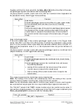
Clocking of the counter can be done with the input clock CLK_TIMT = APB_Takt and
via the SW (internal gate/trigger signal) as well as via an input signal (external
gate/trigger signal)
Triggering of the counter (loading) can be done via the SW (internal gate/trigger signal)
as well as via an input signal (external gate/trigger signal)
Clock output for supplying further modules (bit divider for CLK_TIMT = APB_Clock).
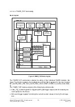
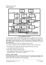
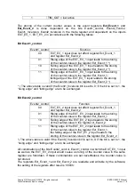
In the zero crossing, an output pulse (TIMER_OUT) is generated which can be evaluated
as interrupt. The TIMER_TOP module contains six TIMER and multiplexer submodules
each for selecting the trigger signals for the individual timers, and functions expanding
over all timers (e.g. synchronous releasing of all timers, address coding). The TIMER
submodule contains the basic timer function (e.g. counter, prescaler, load register for
counter). The distribution of the timer functions to the TIMER and TIMER_TOP modules
is supposed to simplify the reusability in different ASICs.
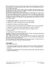
The TIMER and TIMER_TOP modules are described in detail in the following sections.
Connections of the TIMER_TOP module to other modules or to ASIC pins are to be found
in the functional description of the chip/core level.
Содержание ERTEC 200P
Страница 1: ...ERTEC 200P 2 Enhanced Real Time Ethernet Controller Manual ...
Страница 309: ...Copyright Siemens AG 2016 All rights reserved 309 ERTEC 200P 2 Manual Technical data subject to change Version 1 0 ...
Страница 492: ...Copyright Siemens AG 2016 All rights reserved 492 ERTEC 200P 2 Manual Technical data subject to change Version 1 0 ...


