Copyright © Siemens AG 2016. All rights reserved
273
ERTEC 200P-2 Manual
Technical data subject to change
Version 1.0
2.3.10.3.3
Timer module
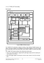
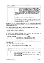
Timer block diagram:
Control Unit
Counter/
Count Register
enable
Load
Register
Int_Event
Register
INT_GATE_TRIG
EXT_EV_2
CLK_TIMT
(32 bit)
(8 bit)
Prescaler
TIM_OUT
Ext_Event_2
Register
Ext_Event_1
Register
* Mode Control
* Gate Control
* Event Control
* Clock Control
Mode
Register
Gate
EXT_GATE_TRIG
EXT_EV_1
COUNTER VALUE
INT_EVENT_VALUE
EVENT_1 VALUE
EVENT_2 VALUE
Prescaler
Register
INT_EV
Address
Decoder
Output
MUX
APB_IF
CLK_EN
Figure 37:TIMER block diagram
The submodules TIMER_TOP and TIMER operate with the operating clock CLK_TIMT or
CLK. CLK_TIMT is wired to CLK. The operating clock is 125MHz and the circuit is de-
signed synchronously with that clock. The reset input of the submodules TIMER_TOP
and TIMER is used as asynchronous reset; a synchronization of the reset input has not
been implemented.
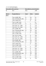
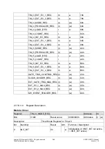
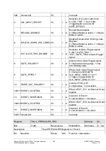
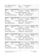
Each TIMER submodule consists of the following functional units:
Counter/count register (counter and register for reading the current counter value)
Prescaler/prescaler register (prescaler and register for prescaler load value)
Load register (load value of the counter)
Mode register (setting the operating mode)
Event register for storing the counter values dependent on events
(register Ext_Event_1, Ext_Event_2, Int_Event)
Counter / counter register:
Each TIMER module contains a 32-bit counter which counts down from a start value. The
counter stops when the value ‘0’ has been reached or is automatically reloaded if the
reload function has been activated in the mode register.
Содержание ERTEC 200P
Страница 1: ...ERTEC 200P 2 Enhanced Real Time Ethernet Controller Manual ...
Страница 309: ...Copyright Siemens AG 2016 All rights reserved 309 ERTEC 200P 2 Manual Technical data subject to change Version 1 0 ...
Страница 492: ...Copyright Siemens AG 2016 All rights reserved 492 ERTEC 200P 2 Manual Technical data subject to change Version 1 0 ...


