


MDS-E/EH Series Instruction Manual
6 Spindle Adjustment
329
IB-1501229-F
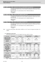
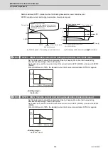
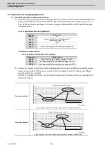
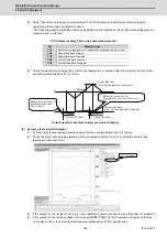
(2) Measuring the acceleration/deceleration waveforms
Measure the speed feedback and current feedback output by setting the monitor output data on "Time-series data
measurement" with NC Analyzer, and check if theoretical acceleration/deceleration time is within ±15%. Refer to
"NC Analyzer Instruction Manual (IB-1501086)" for details on setting the monitor output data.
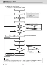
When acceleration/deceleration time does not match the theoretical value (an error rate 15% or more), check the
following items.
[1] There may be an error in calculating load inertia for the motor axis conversion used when calculating the
theoretical acceleration/deceleration time. Check the load inertia again.
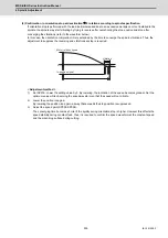
[2] When acceleration time is long and deceleration time is short, friction torque is thought to be large. Check load
meter value at the maximum speed (spindle monitor screen). If the load is 10% or more, friction torque is
thought to be relatively large. Mechanical friction, such as bearing friction or timing belt friction, is assumed to
be large. Measure the acceleration/deceleration time again following trial run.
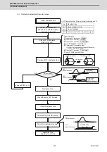
[3] Even if the problems above are not found, when acceleration/deceleration time does not match, there may be
a possibility of using spindle motor and spindle drive unit that are not specified, or using wrong parameters.
Check the spindle motor type and spindle drive unit type again, as well as the spindle parameter settings.
POINT
There are cases where acceleration/deceleration waveforms change depending on the spindle temperature.
Check the waveforms when the spindle temperature is high (after continuous operation) and when it is low.
CAUTION
Vibration or sudden acceleration/deceleration may occur during adjustment. When performing measurement with a
workpiece or tool installed, pay careful attention for the safety during adjustment.
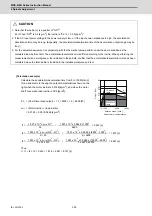
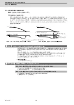
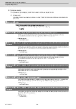
Current feedback
Speed feedback
Acceleration
time:ta
Deceleration
time:td
Acceleration/deceleration characteristics of spindle motor
Measure the time from current rise
to current fall.
Содержание MDS-E
Страница 1: ......
Страница 3: ......
Страница 15: ......
Страница 17: ......
Страница 19: ......
Страница 21: ......
Страница 31: ......
Страница 32: ...1 IB 1501229 F 1 Installation ...
Страница 76: ...45 IB 1501229 F 2 Wiring and Connection ...
Страница 132: ...101 IB 1501229 F 3 Safety Function ...
Страница 142: ...111 IB 1501229 F 4 Setup ...
Страница 277: ...MDS E EH Series Instruction Manual 4 Setup 246 IB 1501229 F ...
Страница 278: ...247 IB 1501229 F 5 Servo Adjustment ...
Страница 351: ...MDS E EH Series Instruction Manual 5 Servo Adjustment 320 IB 1501229 F ...
Страница 352: ...321 IB 1501229 F 6 Spindle Adjustment ...
Страница 404: ...373 IB 1501229 F 7 Troubleshooting ...
Страница 455: ...MDS E EH Series Instruction Manual 7 Troubleshooting 424 IB 1501229 F ...
Страница 456: ...425 IB 1501229 F 8 Maintenance ...
Страница 475: ...MDS E EH Series Instruction Manual 8 Maintenance 444 IB 1501229 F ...
Страница 476: ...445 IB 1501229 F 9 Power Backup System ...
Страница 494: ...463 IB 1501229 F 10 Appx 1 Cable and Connector Assembly ...
Страница 504: ...473 IB 1501229 F 11 Appx 2 D A Output Specifications for Drive Unit ...
Страница 513: ...MDS E EH Series Instruction Manual 11 Appx 2 D A Output Specifications for Drive Unit 482 IB 1501229 F ...
Страница 514: ...483 IB 1501229 F 12 Appx 3 Protection Function ...
Страница 523: ...MDS E EH Series Instruction Manual 12 Appx 3 Protection Function 492 IB 1501229 F ...
Страница 524: ...493 IB 1501229 F 13 Appx 4 Compliance to EC Directives ...
Страница 528: ...497 IB 1501229 F 14 Appx 5 EMC Installation Guidelines ...
Страница 540: ...509 IB 1501229 F 15 Appx 6 Higher Harmonic Suppression Measure Guidelines ...
Страница 545: ...MDS E EH Series Instruction Manual 15 Appx 6 Higher Harmonic Suppression Measure Guidelines 514 IB 1501229 F ...
Страница 550: ......
Страница 554: ......


