MDS-E/EH Series Instruction Manual
2 Wiring and Connection
48
IB-1501229-F
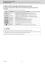
2.2 Main Circuit Terminal Block/Control Circuit Connector
2.2.1 Names and Applications of Main Circuit Terminal Block Signals and Control Circuit
Connectors
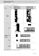
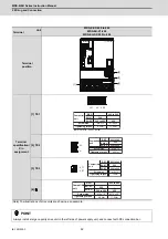
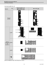
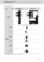
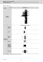
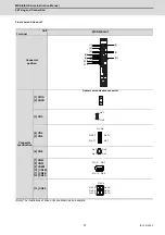
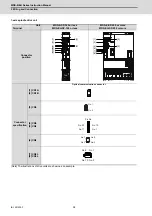
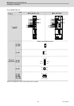
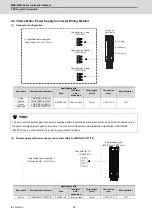
The following table shows the details for each terminal block signal.
Name
Signal name
Description
L1, L2, L3
Main circuit power
supply
Main circuit power supply input terminal
For MDS-E : Connect a 3-phase 200 to 240VAC (50Hz/60Hz) power supply.
For MDS-EH : Connect a 3-phase 380 to 480VAC (50Hz/60Hz) power supply.
L11, L21
Control circuit
power supply
Control circuit power supply input terminal
For MDS-E : Connect a single-phase 200 to 240VAC (50Hz/60Hz) power supply.
For MDS-EH : Connect a single-phase 380 to 480VAC (50Hz/60Hz) power supply.
MC1, MC2
Contactor control
Contactor control terminal
LU, LV, LW
Motor output
(Single-axis unit)
Servo/spindle motor power output terminal
The servo/spindle motor power terminal (U, V, W) is connected.
LU, LV, LW
MU, MV, MW
Motor output
(Dual-axis unit)
Servo/spindle motor power output terminal (L-axis/M-axis)
The servo/spindle motor power terminal (U, V, W) is connected.
LU, LV, LW
MU, MV, MW
SU, SV, SW
Motor output
(Triple-axis unit)
Servo motor power output terminal (L-axis/M-axis/S-axis)
The servo/spindle motor power terminal (U, V, W) is connected.
Protective
grounding (PE)
Grounding terminal
The servo motor/spindle motor grounding terminal is connected and grounded.
CAUTION
1. Always use one AC reactor per power supply unit. Failure to observe this lead to unit damage.
2. When sharing a circuit protector for several power supply units, of a short-circuit fault occurs in a small capacity unit, the
circuit protector could trip. This can be hazardous, so do not share the circuit protector.
3. Be sure to use the circuit protector of proper capacity for each unit.
Содержание MDS-E
Страница 1: ......
Страница 3: ......
Страница 15: ......
Страница 17: ......
Страница 19: ......
Страница 21: ......
Страница 31: ......
Страница 32: ...1 IB 1501229 F 1 Installation ...
Страница 76: ...45 IB 1501229 F 2 Wiring and Connection ...
Страница 132: ...101 IB 1501229 F 3 Safety Function ...
Страница 142: ...111 IB 1501229 F 4 Setup ...
Страница 277: ...MDS E EH Series Instruction Manual 4 Setup 246 IB 1501229 F ...
Страница 278: ...247 IB 1501229 F 5 Servo Adjustment ...
Страница 351: ...MDS E EH Series Instruction Manual 5 Servo Adjustment 320 IB 1501229 F ...
Страница 352: ...321 IB 1501229 F 6 Spindle Adjustment ...
Страница 404: ...373 IB 1501229 F 7 Troubleshooting ...
Страница 455: ...MDS E EH Series Instruction Manual 7 Troubleshooting 424 IB 1501229 F ...
Страница 456: ...425 IB 1501229 F 8 Maintenance ...
Страница 475: ...MDS E EH Series Instruction Manual 8 Maintenance 444 IB 1501229 F ...
Страница 476: ...445 IB 1501229 F 9 Power Backup System ...
Страница 494: ...463 IB 1501229 F 10 Appx 1 Cable and Connector Assembly ...
Страница 504: ...473 IB 1501229 F 11 Appx 2 D A Output Specifications for Drive Unit ...
Страница 513: ...MDS E EH Series Instruction Manual 11 Appx 2 D A Output Specifications for Drive Unit 482 IB 1501229 F ...
Страница 514: ...483 IB 1501229 F 12 Appx 3 Protection Function ...
Страница 523: ...MDS E EH Series Instruction Manual 12 Appx 3 Protection Function 492 IB 1501229 F ...
Страница 524: ...493 IB 1501229 F 13 Appx 4 Compliance to EC Directives ...
Страница 528: ...497 IB 1501229 F 14 Appx 5 EMC Installation Guidelines ...
Страница 540: ...509 IB 1501229 F 15 Appx 6 Higher Harmonic Suppression Measure Guidelines ...
Страница 545: ...MDS E EH Series Instruction Manual 15 Appx 6 Higher Harmonic Suppression Measure Guidelines 514 IB 1501229 F ...
Страница 550: ......
Страница 554: ......

