


MDS-E/EH Series Instruction Manual
2 Wiring and Connection
98
IB-1501229-F
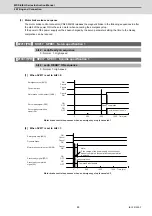
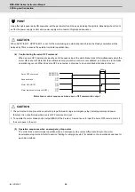
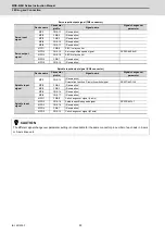
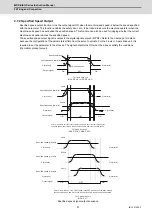
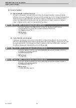
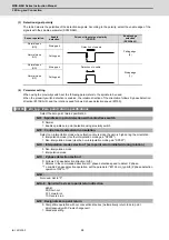
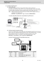
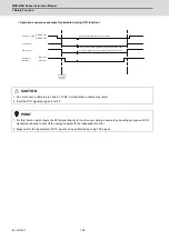
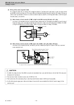
(3) Detection signal polarity
The table below is the polarities of the detections signals. According to the polarity, select the enable edge of the
signals with the spindle parameter (SP225/bit5).
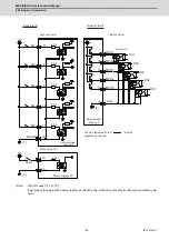
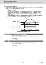
(4) Parameter setting
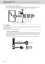
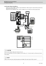
When using the proximity switch, set the following parameters to the spindle to be used.
When the proximity switch detection is enabled, the rotation direction of the orientation follows Z-phase detection
direction (#3106/bit0), and the rotation speed follows Z-phase detection speed (#3109).
【
#3106
】
zrn_typ Zero point return specifications
Select the zero point return specification.
bit F : Spindle zero point detection with contactless switch
0: Normal
1: Enable spindle zero point detection using proximity switch
bit E : Control mode selection in orientation
Select non-interpolation mode when vibration occurs since the gain is high during the orientation.
0: Interpolation mode (Use the interpolation mode gain "SP002".)
1: Non-interpolation mode (Use the non-interpolation mode gain "SP001")
bit D : Interpolation mode selection 1 (zero point return initiated during rotation)
0: Non-interpolation mode
1: Interpolation mode
bit C : Z phase detection method
0: Follows Z phase detection direction (bit0).
1: Rotates in the commanded direction at Z phase detection speed to detect Z phase.
* To enable Z phase detection operation, set the parameter "#3106 zrn_typ bit3 (Z phase detection
operation ON)" to "1".
bit B :
Not used. Set to "0".
bit A-9 : Spindle/C axis zero point return direction
bitA,9=
00: Short-cut
01: Forward run
10: Reverse run
bit 8 : Designate zero point return
0: Compatible operation with our conventional series (Automatically return to zero point
simultaneously with C-axis changeover)
1: Standard setting
Sensor operation
Enable
detection
Drive unit input signal polarity
(CN9 DI1)
Enable edge
selection
(SP225/bit5)
Normal open
(NO)
Rising part
Falling edge
(0)
Normal close
(NC)
Falling part
Normal open
(NO)
Rising part
Rising edge
(1)
Normal close
(NC)
Falling part
Detection of
enable
Detection of
enable
Содержание MDS-E
Страница 1: ......
Страница 3: ......
Страница 15: ......
Страница 17: ......
Страница 19: ......
Страница 21: ......
Страница 31: ......
Страница 32: ...1 IB 1501229 F 1 Installation ...
Страница 76: ...45 IB 1501229 F 2 Wiring and Connection ...
Страница 132: ...101 IB 1501229 F 3 Safety Function ...
Страница 142: ...111 IB 1501229 F 4 Setup ...
Страница 277: ...MDS E EH Series Instruction Manual 4 Setup 246 IB 1501229 F ...
Страница 278: ...247 IB 1501229 F 5 Servo Adjustment ...
Страница 351: ...MDS E EH Series Instruction Manual 5 Servo Adjustment 320 IB 1501229 F ...
Страница 352: ...321 IB 1501229 F 6 Spindle Adjustment ...
Страница 404: ...373 IB 1501229 F 7 Troubleshooting ...
Страница 455: ...MDS E EH Series Instruction Manual 7 Troubleshooting 424 IB 1501229 F ...
Страница 456: ...425 IB 1501229 F 8 Maintenance ...
Страница 475: ...MDS E EH Series Instruction Manual 8 Maintenance 444 IB 1501229 F ...
Страница 476: ...445 IB 1501229 F 9 Power Backup System ...
Страница 494: ...463 IB 1501229 F 10 Appx 1 Cable and Connector Assembly ...
Страница 504: ...473 IB 1501229 F 11 Appx 2 D A Output Specifications for Drive Unit ...
Страница 513: ...MDS E EH Series Instruction Manual 11 Appx 2 D A Output Specifications for Drive Unit 482 IB 1501229 F ...
Страница 514: ...483 IB 1501229 F 12 Appx 3 Protection Function ...
Страница 523: ...MDS E EH Series Instruction Manual 12 Appx 3 Protection Function 492 IB 1501229 F ...
Страница 524: ...493 IB 1501229 F 13 Appx 4 Compliance to EC Directives ...
Страница 528: ...497 IB 1501229 F 14 Appx 5 EMC Installation Guidelines ...
Страница 540: ...509 IB 1501229 F 15 Appx 6 Higher Harmonic Suppression Measure Guidelines ...
Страница 545: ...MDS E EH Series Instruction Manual 15 Appx 6 Higher Harmonic Suppression Measure Guidelines 514 IB 1501229 F ...
Страница 550: ......
Страница 554: ......


