MDS-E/EH Series Instruction Manual
2 Wiring and Connection
62
IB-1501229-F
2.3 NC and Drive Unit Connection
2.3.1 Connection of Optical Communication Cables
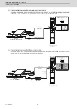
Connect the optical communication cables from the NC to the each drive unit so that they run in a straight line from the
NC to the drive unit that is a final axis. And up to 16 axes can be connected per system.
Note that the number of connected axes is limited by the NC.
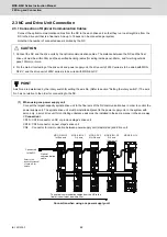
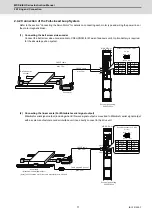
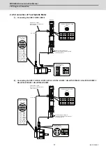
(1) When using one power supply unit
Connect the largest-capacity spindle drive unit to the final axis of the NC communication bus in order to control the
power supply unit. The spindle drive unit must be installed adjacent to the power supply unit. In the system with
servo only, a servo drive unit for controlling unbalance axis must be installed in the same manner in the same way.
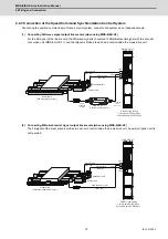
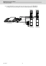
< Connection >
CN1A : CN1B connector on NC or previous stage's drive unit
CN1B : CN1A connector on next stage's drive unit
CN4 : Connector for communication between power supply unit (master side) and drive unit
Connection when using one power supply unit
CAUTION
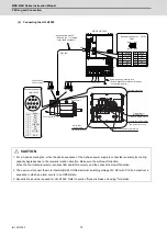
1. Connect the NC and the drive units by the optical communication cables. The distance between the NC and the final
drive unit must be within 30m and the specified bending radius (for wiring inside panel: 25mm, and for wiring outside
panel: 50mm) or more.
2. For the main circuit wiring of the drive unit and power supply unit, the drive unit of 200V series is to be wired with MDS-
D2-CV, and the drive unit of 400V series is to be wired with MDS-EH-CV.
POINT
Axis Nos. are determined by the rotary switch for setting the axis No. (Refer to section "Setting the rotary switch".) The axis
No. has no relation to the order for connecting to the NC.
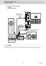
CN4
CN4
Refer to the
instruction manual
of each NC for
details.
The optical communication cables from the NC to the
final drive unit must be within 30m.
Optical
communication
cable
Connected
to the NC
MDS-E/EH-V2
1st/2nd axis
MDS-E/EH-V1
3rd axis
MDS-E/EH-SP
6th axis
(Final axis)
MDS-E/EH-CV
MDS-E-SP2
4th/5th axis
Содержание MDS-E
Страница 1: ......
Страница 3: ......
Страница 15: ......
Страница 17: ......
Страница 19: ......
Страница 21: ......
Страница 31: ......
Страница 32: ...1 IB 1501229 F 1 Installation ...
Страница 76: ...45 IB 1501229 F 2 Wiring and Connection ...
Страница 132: ...101 IB 1501229 F 3 Safety Function ...
Страница 142: ...111 IB 1501229 F 4 Setup ...
Страница 277: ...MDS E EH Series Instruction Manual 4 Setup 246 IB 1501229 F ...
Страница 278: ...247 IB 1501229 F 5 Servo Adjustment ...
Страница 351: ...MDS E EH Series Instruction Manual 5 Servo Adjustment 320 IB 1501229 F ...
Страница 352: ...321 IB 1501229 F 6 Spindle Adjustment ...
Страница 404: ...373 IB 1501229 F 7 Troubleshooting ...
Страница 455: ...MDS E EH Series Instruction Manual 7 Troubleshooting 424 IB 1501229 F ...
Страница 456: ...425 IB 1501229 F 8 Maintenance ...
Страница 475: ...MDS E EH Series Instruction Manual 8 Maintenance 444 IB 1501229 F ...
Страница 476: ...445 IB 1501229 F 9 Power Backup System ...
Страница 494: ...463 IB 1501229 F 10 Appx 1 Cable and Connector Assembly ...
Страница 504: ...473 IB 1501229 F 11 Appx 2 D A Output Specifications for Drive Unit ...
Страница 513: ...MDS E EH Series Instruction Manual 11 Appx 2 D A Output Specifications for Drive Unit 482 IB 1501229 F ...
Страница 514: ...483 IB 1501229 F 12 Appx 3 Protection Function ...
Страница 523: ...MDS E EH Series Instruction Manual 12 Appx 3 Protection Function 492 IB 1501229 F ...
Страница 524: ...493 IB 1501229 F 13 Appx 4 Compliance to EC Directives ...
Страница 528: ...497 IB 1501229 F 14 Appx 5 EMC Installation Guidelines ...
Страница 540: ...509 IB 1501229 F 15 Appx 6 Higher Harmonic Suppression Measure Guidelines ...
Страница 545: ...MDS E EH Series Instruction Manual 15 Appx 6 Higher Harmonic Suppression Measure Guidelines 514 IB 1501229 F ...
Страница 550: ......
Страница 554: ......

