MDS-E/EH Series Instruction Manual
10 Appx. 1: Cable and Connector Assembly
465
IB-1501229-F
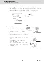
(Note)
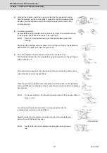
Make sure that the core wire does not come out of the contact.
When soldering, make sure that the solder does not stick to the circumference of the solder cup.
When using a drain wire, attach a heat shrink tube to the drain cable after soldering.
*
When making CMV1-xP10S-xx, the cable for No. 10 terminal is 1mm longer than other cables. (To avoid
the core tension when inserting a contact to the housing in a later process.)
*
The difference in the total A length of the cables for other than No. 10 terminal must be 1mm or less.
(5) Inserting the contact
Insert the contact into the specified terminal number point in
the housing.
(Insert grounding wire or drain wire into terminal No. 10).
*
When the contact catches the housing, you will hear
a snap.
*
Pulling the wire for confirming the correct position.
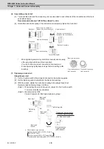
(Note)
Before inserting the contact, check that the clamp nut, cable clamp, bushing and back shell is inserted.
Take care not to insert the contact upside down as shown below.
*
Insert the contact so that the terminal number face the same
direction.
*
Using a pull out tool for pulling up inserted contact.
Tool No.: 357J-53184T
Refer to the instruction manual in case of using pull up tool.
*
As Lance falls down easily after pulling up, set up to original
position before re-insert.
C
Detail C
Solder
Contact
Core wire
Cable
Drain wire
Heat shrink tube
Difference in total length: 1 mm or less
(for other than No. 10 terminal)
If a drain wire is soldered
Cable
Housing
Contact
Terminal No.10 only
(Grounding wire or drain wire)
Insert
Terminal number
Lance
Contact
Terminal number
Lance
Contact
CMV1-xP2S-xx
CMV1-xP10S-xx
Содержание MDS-E
Страница 1: ......
Страница 3: ......
Страница 15: ......
Страница 17: ......
Страница 19: ......
Страница 21: ......
Страница 31: ......
Страница 32: ...1 IB 1501229 F 1 Installation ...
Страница 76: ...45 IB 1501229 F 2 Wiring and Connection ...
Страница 132: ...101 IB 1501229 F 3 Safety Function ...
Страница 142: ...111 IB 1501229 F 4 Setup ...
Страница 277: ...MDS E EH Series Instruction Manual 4 Setup 246 IB 1501229 F ...
Страница 278: ...247 IB 1501229 F 5 Servo Adjustment ...
Страница 351: ...MDS E EH Series Instruction Manual 5 Servo Adjustment 320 IB 1501229 F ...
Страница 352: ...321 IB 1501229 F 6 Spindle Adjustment ...
Страница 404: ...373 IB 1501229 F 7 Troubleshooting ...
Страница 455: ...MDS E EH Series Instruction Manual 7 Troubleshooting 424 IB 1501229 F ...
Страница 456: ...425 IB 1501229 F 8 Maintenance ...
Страница 475: ...MDS E EH Series Instruction Manual 8 Maintenance 444 IB 1501229 F ...
Страница 476: ...445 IB 1501229 F 9 Power Backup System ...
Страница 494: ...463 IB 1501229 F 10 Appx 1 Cable and Connector Assembly ...
Страница 504: ...473 IB 1501229 F 11 Appx 2 D A Output Specifications for Drive Unit ...
Страница 513: ...MDS E EH Series Instruction Manual 11 Appx 2 D A Output Specifications for Drive Unit 482 IB 1501229 F ...
Страница 514: ...483 IB 1501229 F 12 Appx 3 Protection Function ...
Страница 523: ...MDS E EH Series Instruction Manual 12 Appx 3 Protection Function 492 IB 1501229 F ...
Страница 524: ...493 IB 1501229 F 13 Appx 4 Compliance to EC Directives ...
Страница 528: ...497 IB 1501229 F 14 Appx 5 EMC Installation Guidelines ...
Страница 540: ...509 IB 1501229 F 15 Appx 6 Higher Harmonic Suppression Measure Guidelines ...
Страница 545: ...MDS E EH Series Instruction Manual 15 Appx 6 Higher Harmonic Suppression Measure Guidelines 514 IB 1501229 F ...
Страница 550: ......
Страница 554: ......

