MDS-E/EH Series Instruction Manual
14 Appx. 5: EMC Installation Guidelines
502
IB-1501229-F
14.5.3 Servo/Spindle Motor Power Cable
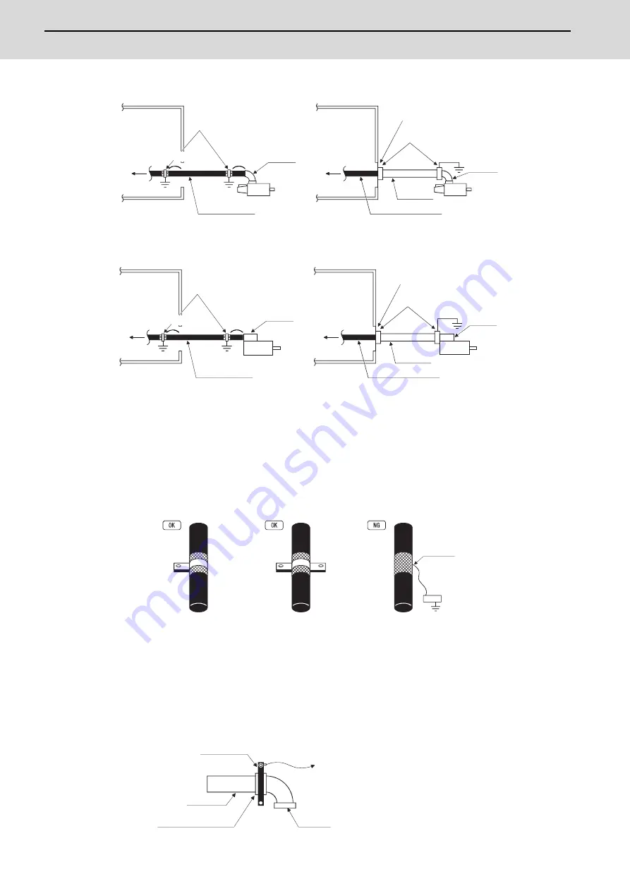
Power cable for servo motor
Power cable for spindle motor
[1] Use four wires (3-phase + earthing) for the power cable that are completely shielded and free from breaks.
[2] Earth the shield on both the control panel side and motor chassis side. The shield earth position on the drive unit
side must be 10cm or less from the control panel.
[3] Earth the shield with a metal P clip or U clip.
(A cable clamp fitting can be used depending on the wire size.)
[4] Directly earth the shield. Do not solder the braided shield onto a wire and earth the end of the wire.
[5] When not using a shield cable for the power cable, use a conventional cabtyre cable. Use a metal conduit outside
the cable.
[6] Earth the power cable on the control panel side at the contact surface of the conduit connector and control panel.
(Mask the side wall of the control panel with paint.)
[7] Follow the treatment shown in the example for the conduit connector to earth the power cable on the motor side.
(Example: Use a clamp fitting, etc.)
To drive unit
Earth with P or U clip
Cannon
connector
Shield cable
Servo motor
Control panel
Earth with paint mask
Conduit connector
Servo motor
Cabtyre cable
Conduit
Using shield cable
Using conduit
Control panel
To drive unit
Cannon
connector
10cm or less
As close
as possible
Control panel
Terminal box
Spindle motor
Earth with paint mask
Conduit connector
Control panel
To drive unit
To drive unit
Using shield cable
Shield cable
Earth with P or U clip
Using conduit
Cabtyre cable
Spindle motor
Conduit
Terminal box
10cm or less
As close
as possible
Solder
Earth example with P clip
Earth example with U clip
Earth example with wire soldering
Earth (Wire it as short and thick as possible.)
Conduit connector
Connector
Clamp fitting
Conduit
Содержание MDS-E
Страница 1: ......
Страница 3: ......
Страница 15: ......
Страница 17: ......
Страница 19: ......
Страница 21: ......
Страница 31: ......
Страница 32: ...1 IB 1501229 F 1 Installation ...
Страница 76: ...45 IB 1501229 F 2 Wiring and Connection ...
Страница 132: ...101 IB 1501229 F 3 Safety Function ...
Страница 142: ...111 IB 1501229 F 4 Setup ...
Страница 277: ...MDS E EH Series Instruction Manual 4 Setup 246 IB 1501229 F ...
Страница 278: ...247 IB 1501229 F 5 Servo Adjustment ...
Страница 351: ...MDS E EH Series Instruction Manual 5 Servo Adjustment 320 IB 1501229 F ...
Страница 352: ...321 IB 1501229 F 6 Spindle Adjustment ...
Страница 404: ...373 IB 1501229 F 7 Troubleshooting ...
Страница 455: ...MDS E EH Series Instruction Manual 7 Troubleshooting 424 IB 1501229 F ...
Страница 456: ...425 IB 1501229 F 8 Maintenance ...
Страница 475: ...MDS E EH Series Instruction Manual 8 Maintenance 444 IB 1501229 F ...
Страница 476: ...445 IB 1501229 F 9 Power Backup System ...
Страница 494: ...463 IB 1501229 F 10 Appx 1 Cable and Connector Assembly ...
Страница 504: ...473 IB 1501229 F 11 Appx 2 D A Output Specifications for Drive Unit ...
Страница 513: ...MDS E EH Series Instruction Manual 11 Appx 2 D A Output Specifications for Drive Unit 482 IB 1501229 F ...
Страница 514: ...483 IB 1501229 F 12 Appx 3 Protection Function ...
Страница 523: ...MDS E EH Series Instruction Manual 12 Appx 3 Protection Function 492 IB 1501229 F ...
Страница 524: ...493 IB 1501229 F 13 Appx 4 Compliance to EC Directives ...
Страница 528: ...497 IB 1501229 F 14 Appx 5 EMC Installation Guidelines ...
Страница 540: ...509 IB 1501229 F 15 Appx 6 Higher Harmonic Suppression Measure Guidelines ...
Страница 545: ...MDS E EH Series Instruction Manual 15 Appx 6 Higher Harmonic Suppression Measure Guidelines 514 IB 1501229 F ...
Страница 550: ......
Страница 554: ......

