MDS-E/EH Series Instruction Manual
10 Appx. 1: Cable and Connector Assembly
470
IB-1501229-F
10.2 1747464-1 Plug Connector
10.2.1 Applicable Products
10.2.2 Applicable Cable
Refer to Product Specification and Application Specification for details.
10.2.3 Related Documents
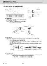
10.2.4 Assembly Procedure
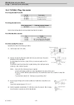
Assemble the cable in the following procedure:
(1) Insert accessories to the cable.
(2) Remove the sheath of the cable jacket and core wires referring to the typical
dimensions in the right figure.
Do not damage the core wires. Retry it if the core wires are partly cut off or
damaged.
The length of mesh shield should be decided referring to the right figure and be
turned up on the outside of a jacket.
(Note)
Even when the dimensions above is applied,
product performance problem can occur depending on the wires which is used.
Be sure to contact with the sales department of the manufacturer below if you consider to adopt this
connector.
Tyco Electronics Japan G.K. http://www.te.com/en/home.html
(3) Twist a copper foil tape with conductive adhesive of width 5mm around the mesh
shield.
Cable finish outside diameter:
Φ
7.3 to 7.7
(4) Refer to Application Specification (114-5335) and crimp the contacts. After crimping,
check the state in accordance with the Specification.
Part No.
Descriptions
1674320-1
1674320-2
Encoder cable I/O kit
1674335-4
Receptacle contact
Wire conductor size
Cable jacket outside diameter
#26-22AWG
6.8 to 7.4 mm
No.
Details
108-5864
Product Specification
114-5335
Rec, Contact Application Specification
114-5338
Ground Clip Application Specification
Receptacle case assembly
Wire clamp
Wire fixed set screw
Wire rubber packing
Ground clip
Cable
14
±1
mm
16
±1
mm
4
to
5mm
1.6
to
2.0mm
1.6
to
2.0mm
Mesh shield
Far side
Near side
6mm MAX
Φ7.3
to
7.7
Copper foil tape
Receptacle contact
Содержание MDS-E
Страница 1: ......
Страница 3: ......
Страница 15: ......
Страница 17: ......
Страница 19: ......
Страница 21: ......
Страница 31: ......
Страница 32: ...1 IB 1501229 F 1 Installation ...
Страница 76: ...45 IB 1501229 F 2 Wiring and Connection ...
Страница 132: ...101 IB 1501229 F 3 Safety Function ...
Страница 142: ...111 IB 1501229 F 4 Setup ...
Страница 277: ...MDS E EH Series Instruction Manual 4 Setup 246 IB 1501229 F ...
Страница 278: ...247 IB 1501229 F 5 Servo Adjustment ...
Страница 351: ...MDS E EH Series Instruction Manual 5 Servo Adjustment 320 IB 1501229 F ...
Страница 352: ...321 IB 1501229 F 6 Spindle Adjustment ...
Страница 404: ...373 IB 1501229 F 7 Troubleshooting ...
Страница 455: ...MDS E EH Series Instruction Manual 7 Troubleshooting 424 IB 1501229 F ...
Страница 456: ...425 IB 1501229 F 8 Maintenance ...
Страница 475: ...MDS E EH Series Instruction Manual 8 Maintenance 444 IB 1501229 F ...
Страница 476: ...445 IB 1501229 F 9 Power Backup System ...
Страница 494: ...463 IB 1501229 F 10 Appx 1 Cable and Connector Assembly ...
Страница 504: ...473 IB 1501229 F 11 Appx 2 D A Output Specifications for Drive Unit ...
Страница 513: ...MDS E EH Series Instruction Manual 11 Appx 2 D A Output Specifications for Drive Unit 482 IB 1501229 F ...
Страница 514: ...483 IB 1501229 F 12 Appx 3 Protection Function ...
Страница 523: ...MDS E EH Series Instruction Manual 12 Appx 3 Protection Function 492 IB 1501229 F ...
Страница 524: ...493 IB 1501229 F 13 Appx 4 Compliance to EC Directives ...
Страница 528: ...497 IB 1501229 F 14 Appx 5 EMC Installation Guidelines ...
Страница 540: ...509 IB 1501229 F 15 Appx 6 Higher Harmonic Suppression Measure Guidelines ...
Страница 545: ...MDS E EH Series Instruction Manual 15 Appx 6 Higher Harmonic Suppression Measure Guidelines 514 IB 1501229 F ...
Страница 550: ......
Страница 554: ......

