

MDS-E/EH Series Instruction Manual
4 Setup
132
IB-1501229-F
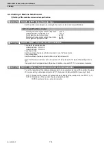
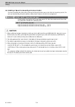
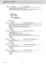
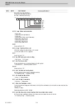
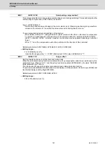
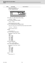
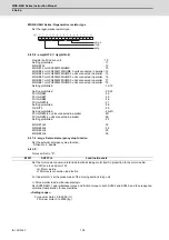
Set the speed loop gain at the motor limitation speed VLMT (maximum rotation speed x 1.15) with
"VCS(SV029: Speed at the change of speed loop gain)".
Use this to suppress noise at high speed rotation during rapid traverse, etc. Then, the speed loop gain de-
creases at faster speed than the setting value of VCS. When not using, set to "0".
---Setting range---
-1000 to 30000
Set this when the limit cycle occurs in the full-closed loop, or overshooting occurs in positioning. The speed
loop delay compensation method can be selected with SV027/bit1,0.
Normally, use "Changeover type 2". Changeover type 2 controls the occurrence of overshooting by lowering
the speed loop lead compensation after the position droop gets 0.
When setting this parameter, make sure to set the torque offset (SV032).
---Setting range---
0 to 32767
Set the gain of the speed loop integral control.
Standard setting: 1364
Standard setting in the SHG control: 1900
Adjust the value by increasing/decreasing this by about 100 at a time.
Raise this value to improve contour tracking accuracy in high-speed cutting.
Lower this value when the position droop does not stabilize (when the vibration of 10 to 20Hz occurs).
---Setting range---
1 to 9999
Set the fixed value of each motor.
Set the standard value for each motor described in the standard parameter list.
---Setting range---
1 to 20480
Set the fixed value of each motor.
Set the standard value for each motor described in the standard parameter list.
---Setting range---
1 to 20480
Set the fixed value of each motor.
Set the standard value for each motor described in the standard parameter list.
---Setting range---
1 to 8192
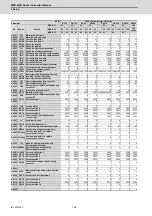
#2206
SV006 VGN2
Speed loop gain 2
#2207
SV007 VIL
Speed loop delay compensation
#2208
SV008 VIA
Speed loop lead compensation
#2209
SV009 IQA
Current loop q axis lead compensation
#2210
SV010 IDA
Current loop d axis lead compensation
#2211
SV011 IQG
Current loop q axis gain
VGN1
VGN2
VCS
VLMT
0
Gain
Speed
(Overspeed detection speed)
Содержание MDS-E
Страница 1: ......
Страница 3: ......
Страница 15: ......
Страница 17: ......
Страница 19: ......
Страница 21: ......
Страница 31: ......
Страница 32: ...1 IB 1501229 F 1 Installation ...
Страница 76: ...45 IB 1501229 F 2 Wiring and Connection ...
Страница 132: ...101 IB 1501229 F 3 Safety Function ...
Страница 142: ...111 IB 1501229 F 4 Setup ...
Страница 277: ...MDS E EH Series Instruction Manual 4 Setup 246 IB 1501229 F ...
Страница 278: ...247 IB 1501229 F 5 Servo Adjustment ...
Страница 351: ...MDS E EH Series Instruction Manual 5 Servo Adjustment 320 IB 1501229 F ...
Страница 352: ...321 IB 1501229 F 6 Spindle Adjustment ...
Страница 404: ...373 IB 1501229 F 7 Troubleshooting ...
Страница 455: ...MDS E EH Series Instruction Manual 7 Troubleshooting 424 IB 1501229 F ...
Страница 456: ...425 IB 1501229 F 8 Maintenance ...
Страница 475: ...MDS E EH Series Instruction Manual 8 Maintenance 444 IB 1501229 F ...
Страница 476: ...445 IB 1501229 F 9 Power Backup System ...
Страница 494: ...463 IB 1501229 F 10 Appx 1 Cable and Connector Assembly ...
Страница 504: ...473 IB 1501229 F 11 Appx 2 D A Output Specifications for Drive Unit ...
Страница 513: ...MDS E EH Series Instruction Manual 11 Appx 2 D A Output Specifications for Drive Unit 482 IB 1501229 F ...
Страница 514: ...483 IB 1501229 F 12 Appx 3 Protection Function ...
Страница 523: ...MDS E EH Series Instruction Manual 12 Appx 3 Protection Function 492 IB 1501229 F ...
Страница 524: ...493 IB 1501229 F 13 Appx 4 Compliance to EC Directives ...
Страница 528: ...497 IB 1501229 F 14 Appx 5 EMC Installation Guidelines ...
Страница 540: ...509 IB 1501229 F 15 Appx 6 Higher Harmonic Suppression Measure Guidelines ...
Страница 545: ...MDS E EH Series Instruction Manual 15 Appx 6 Higher Harmonic Suppression Measure Guidelines 514 IB 1501229 F ...
Страница 550: ......
Страница 554: ......


