MDS-E/EH Series Instruction Manual
12 Appx. 3: Protection Function
487
IB-1501229-F
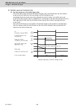
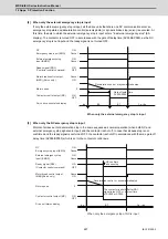
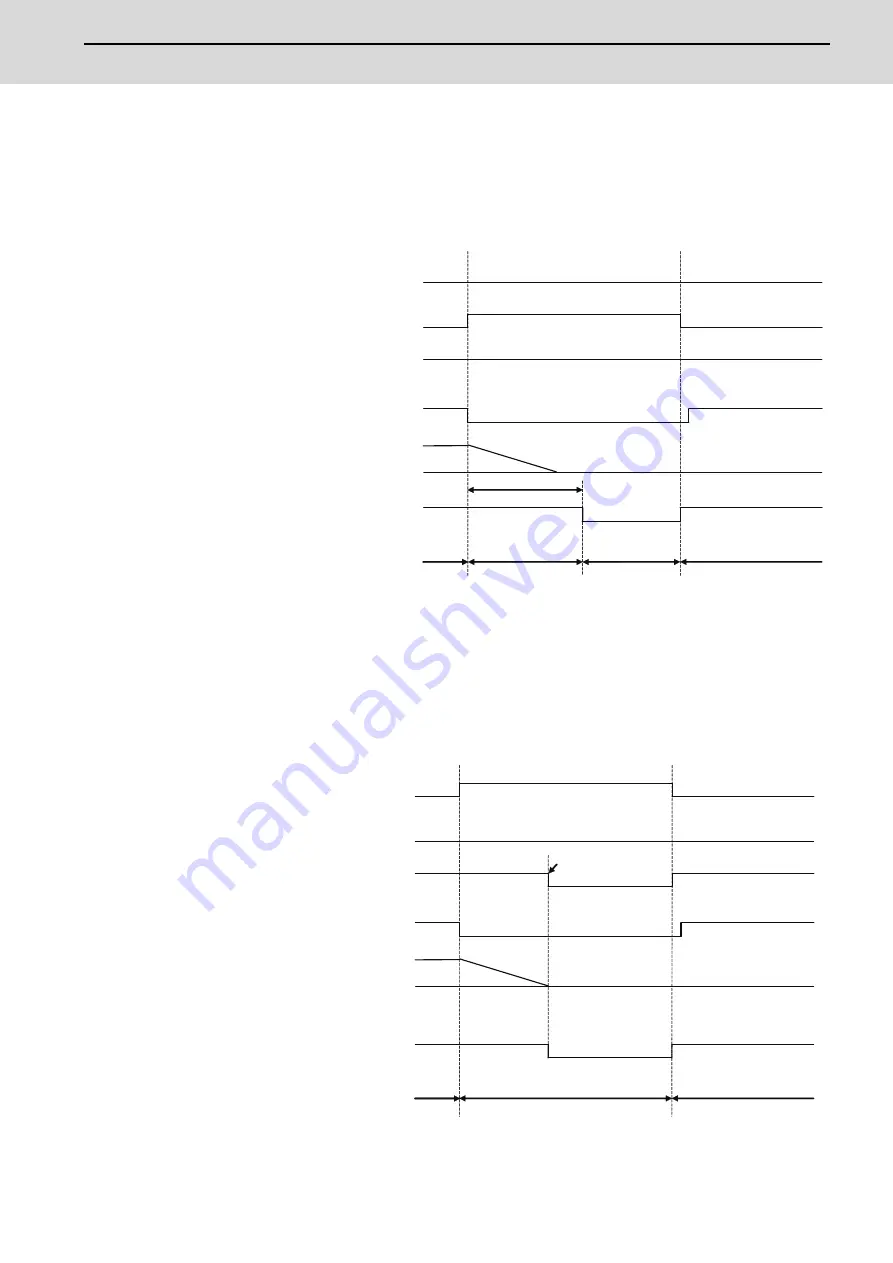
[2] When only the external emergency stop is input
If only the external emergency stop is input, all the drive units that share one NC communication enter an
emergency stop state and deceleration control (servo/spindle) or dynamic brake stop (servo) is executed. At
this time, the axis to which the external emergency stop is input enters "in external emergency stop" (EA
display). The contactor is turned OFF in accordance with the gate off delay time (SV055/SP055), as the NC
emergency stop is not input and the ready signal is not turned OFF.
[3] When only the NC emergency stop is input
Motors of all axes enter deceleration stop in the same sequence as normal operation (when both NC and
external emergency stop signals are input) and the contactor is shut off. In case that all axes stop is not
confirmed and the ready signal is not turned OFF, the contactor is shut off in accordance with the max. gate off
delay time (SV055/SP055) which is set to the contactor control axis.
ON
OFF
0
dx
Cx→dx
EA
E7
ON
OFF
Deceleration control, or dynamic brake stop
NC
Emergency stop input (EMG)
External emergency stop
input (EMGX)
Motor break control output
(MBR) (Servo only)
Motor speed
Contactor control output (MC)
Servo drive unit status display
When only the external emergency stop is input
Gate off delay time
SV055/SP055
ON
Cancel
ON
Cancel
Cancel
ON
Ready signal (RDY)
(
Contactor control command
)
ON
OFF
0
ON
OFF
dx
Cx→dx
E7
NC
Emergency stop input (EMG)
External emergency stop
input (EMGX)
Motor break control output
(MBR)(Servo only)
Motor speed
Contactor control output (MC)
Drive unit status display
When only the emergency stop of NC is input
ON
Cancel
ON
Cancel
Cancel
ON
Ready signal (RDY)
(
Contactor control command
)
NC confirms
all axes stop
Deceleration control, or dynamic brake stop
The contactor is shut off after RDY
signal turns OFF, or after set time
of SV055 or SP055.
Содержание MDS-E
Страница 1: ......
Страница 3: ......
Страница 15: ......
Страница 17: ......
Страница 19: ......
Страница 21: ......
Страница 31: ......
Страница 32: ...1 IB 1501229 F 1 Installation ...
Страница 76: ...45 IB 1501229 F 2 Wiring and Connection ...
Страница 132: ...101 IB 1501229 F 3 Safety Function ...
Страница 142: ...111 IB 1501229 F 4 Setup ...
Страница 277: ...MDS E EH Series Instruction Manual 4 Setup 246 IB 1501229 F ...
Страница 278: ...247 IB 1501229 F 5 Servo Adjustment ...
Страница 351: ...MDS E EH Series Instruction Manual 5 Servo Adjustment 320 IB 1501229 F ...
Страница 352: ...321 IB 1501229 F 6 Spindle Adjustment ...
Страница 404: ...373 IB 1501229 F 7 Troubleshooting ...
Страница 455: ...MDS E EH Series Instruction Manual 7 Troubleshooting 424 IB 1501229 F ...
Страница 456: ...425 IB 1501229 F 8 Maintenance ...
Страница 475: ...MDS E EH Series Instruction Manual 8 Maintenance 444 IB 1501229 F ...
Страница 476: ...445 IB 1501229 F 9 Power Backup System ...
Страница 494: ...463 IB 1501229 F 10 Appx 1 Cable and Connector Assembly ...
Страница 504: ...473 IB 1501229 F 11 Appx 2 D A Output Specifications for Drive Unit ...
Страница 513: ...MDS E EH Series Instruction Manual 11 Appx 2 D A Output Specifications for Drive Unit 482 IB 1501229 F ...
Страница 514: ...483 IB 1501229 F 12 Appx 3 Protection Function ...
Страница 523: ...MDS E EH Series Instruction Manual 12 Appx 3 Protection Function 492 IB 1501229 F ...
Страница 524: ...493 IB 1501229 F 13 Appx 4 Compliance to EC Directives ...
Страница 528: ...497 IB 1501229 F 14 Appx 5 EMC Installation Guidelines ...
Страница 540: ...509 IB 1501229 F 15 Appx 6 Higher Harmonic Suppression Measure Guidelines ...
Страница 545: ...MDS E EH Series Instruction Manual 15 Appx 6 Higher Harmonic Suppression Measure Guidelines 514 IB 1501229 F ...
Страница 550: ......
Страница 554: ......

