


MDS-E/EH Series Instruction Manual
4 Setup
213
IB-1501229-F
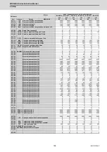
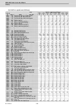
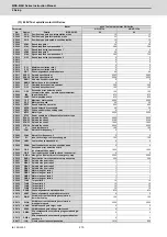
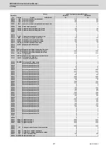
4.3.3 Spindle Parameters
These parameters are sent to the spindle drive unit when the NC power is turned ON. The standard parameters are des-
ignated with the "Spindle parameter setting list" enclosed when the spindle motor is delivered. There may be cases when
the machine specifications are unclear, so the parameters determined by the machine specifications should be confirmed
by the user.
The parameters with "(PR)" requires the CNC to be turned OFF after the settings. Turn the power OFF and ON to enable
the parameter settings.
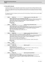
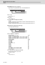
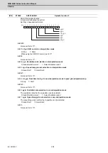
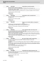
Set the position loop gain for "Non-interpolation" control mode.
When the setting value increases, the command tracking ability will enhance and the positioning settling time
can be shorter. However, the impact on the machine during acceleration/deceleration will increase.
Use the selection command, the control mode "bit 2, 1, 0 = 000" in control input 4.
(Note) The control mode is commanded by NC.
---Setting range---
1 to 200 (rad/s)
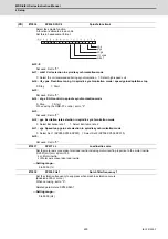
Set the position loop gain for "interpolation" control mode.
When the setting value increases, the command tracking ability will enhance and the positioning settling time
can be shorter. However, the impact on the machine during acceleration/deceleration will increase.
Use the selection command, the control mode "bit 2, 1, 0 = 010 or 100" in control input 4.
(Note) The control mode is commanded by NC.
When carrying out the SHG control, set SP035/bitC to "1".
---Setting range---
1 to 200 (rad/s)
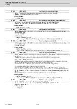
Set the position loop gain for "spindle synchronization" control mode.
When the setting value increases, the command tracking ability will enhance and the positioning settling time
can be shorter. However, the impact on the machine during acceleration/deceleration will increase.
Use the selection command, the control mode "bit 2, 1, 0 = 001" in control input 4.
(Note 1) The control mode is commanded by NC.
When carrying out the SHG control, set SP036/bit4 to "1".
(Note 2) Set the same value for the basic and synchronous spindles in spindle synchronization.
---Setting range---
1 to 200 (rad/s)
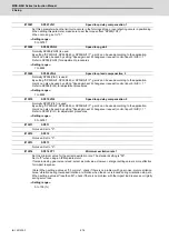
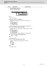
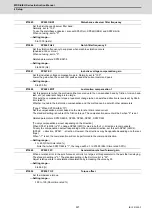
Not used. Set to "0".
Set the speed loop gain.
Set this according to the load inertia size.
The higher setting value will increase the accuracy of control, however, vibration tends to occur.
If vibration occurs, adjust by lowering by 20 to 30%.
The final value should be 70 to 80% of the value at which the vibration stops.
---Setting range---
1 to 9999
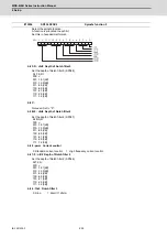
Set the speed loop integral control gain.
The standard setting is "1900". Adjust the value by increasing/decreasing the value by about 100.
Raise this value to improve the contour tracking accuracy in high-speed cutting.
Lower this value when the position droop does not stabilize (when the vibration of 10 to 20Hz occurs).
---Setting range---
1 to 9999
#13001
SP001 PGV
Position loop gain non-interpolation mode
#13002
SP002 PGN
Position loop gain interpolation mode
#13003
SP003 PGS
Position loop gain spindle synchronization
#13004
SP004
#13005
SP005 VGN1
Speed loop gain 1
#13006
SP006 VIA1
Speed loop lead compensation 1
Содержание MDS-E
Страница 1: ......
Страница 3: ......
Страница 15: ......
Страница 17: ......
Страница 19: ......
Страница 21: ......
Страница 31: ......
Страница 32: ...1 IB 1501229 F 1 Installation ...
Страница 76: ...45 IB 1501229 F 2 Wiring and Connection ...
Страница 132: ...101 IB 1501229 F 3 Safety Function ...
Страница 142: ...111 IB 1501229 F 4 Setup ...
Страница 277: ...MDS E EH Series Instruction Manual 4 Setup 246 IB 1501229 F ...
Страница 278: ...247 IB 1501229 F 5 Servo Adjustment ...
Страница 351: ...MDS E EH Series Instruction Manual 5 Servo Adjustment 320 IB 1501229 F ...
Страница 352: ...321 IB 1501229 F 6 Spindle Adjustment ...
Страница 404: ...373 IB 1501229 F 7 Troubleshooting ...
Страница 455: ...MDS E EH Series Instruction Manual 7 Troubleshooting 424 IB 1501229 F ...
Страница 456: ...425 IB 1501229 F 8 Maintenance ...
Страница 475: ...MDS E EH Series Instruction Manual 8 Maintenance 444 IB 1501229 F ...
Страница 476: ...445 IB 1501229 F 9 Power Backup System ...
Страница 494: ...463 IB 1501229 F 10 Appx 1 Cable and Connector Assembly ...
Страница 504: ...473 IB 1501229 F 11 Appx 2 D A Output Specifications for Drive Unit ...
Страница 513: ...MDS E EH Series Instruction Manual 11 Appx 2 D A Output Specifications for Drive Unit 482 IB 1501229 F ...
Страница 514: ...483 IB 1501229 F 12 Appx 3 Protection Function ...
Страница 523: ...MDS E EH Series Instruction Manual 12 Appx 3 Protection Function 492 IB 1501229 F ...
Страница 524: ...493 IB 1501229 F 13 Appx 4 Compliance to EC Directives ...
Страница 528: ...497 IB 1501229 F 14 Appx 5 EMC Installation Guidelines ...
Страница 540: ...509 IB 1501229 F 15 Appx 6 Higher Harmonic Suppression Measure Guidelines ...
Страница 545: ...MDS E EH Series Instruction Manual 15 Appx 6 Higher Harmonic Suppression Measure Guidelines 514 IB 1501229 F ...
Страница 550: ......
Страница 554: ......


