


MDS-E/EH Series Instruction Manual
4 Setup
115
IB-1501229-F
4.2 Setting the Initial Parameters for the Servo Drive Unit
The servo parameters must be set before the servo system can be started up. The servo parameters are input from the
NC. The input method differs according to the NC being used, so refer to each NC Instruction Manual.
When setting the initial setting parameters, perform the following settings in each system.
<For semi closed loop control (single-axis control)>
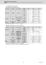
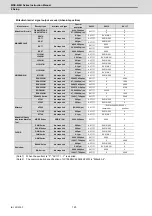
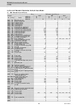
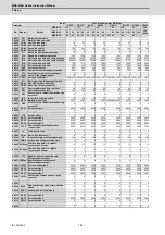
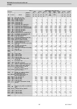
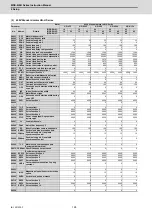
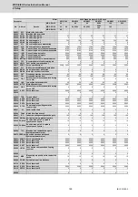
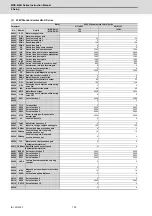
(1) Set the standard parameters in the section "4.2.5 List of Standard Parameters for Each Servo Motor".
(2) "4.2.1 Setting of Servo Specification Parameters"
< For full closed loop control (single-axis control) >
(1) Set the standard parameters in the section "4.2.5 List of Standard Parameters for Each Servo Motor".
(2) "4.2.1 Setting of Servo Specification Parameters"
(3) "4.2.2 Setting of Machine Side Encoder"
<For full closed loop control with a distance-coded reference scale (single-axis control)>
(1) Set the standard parameters in the section "4.2.5 List of Standard Parameters for Each Servo Motor".
(2) "4.2.1 Setting of Servo Specification Parameters"
(3) "4.2.2 Setting of Machine Side Encoder"
(4) "4.2.3 Setting of Distance-coded Reference Scale"
< For speed command synchronous control >
(1) Set the standard parameters in the section "4.2.5 List of Standard Parameters for Each Servo Motor".
(2) "4.2.1 Setting of Servo Specification Parameters"
(3) "4.2.2 Setting of Machine Side Encoder"
(4) "4.2.4 Setting of Speed Command Synchronous Control"
(Note)
For the position command synchronous control, perform the items of single-axis control for each axis.
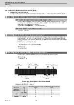
Setting the initial parameters above enables the test operation for the servo axis (Ex. manual pulse feed, low-speed JOG
feed). When machine resonance occurs, check the machine resonance frequency at AFLT frequency on the drive
monitor screen and set to the following servo parameters (When the AFLT frequency displays "0", resonance is not
occurring).
【
#2238
】
SV038 FHz1 Notch filter frequency 1
Set the vibration frequency to suppress when machine vibration occurs.
(Normally, do not set 80 or less.)
---Setting range---
0 to 5000 (Hz)
Содержание MDS-E
Страница 1: ......
Страница 3: ......
Страница 15: ......
Страница 17: ......
Страница 19: ......
Страница 21: ......
Страница 31: ......
Страница 32: ...1 IB 1501229 F 1 Installation ...
Страница 76: ...45 IB 1501229 F 2 Wiring and Connection ...
Страница 132: ...101 IB 1501229 F 3 Safety Function ...
Страница 142: ...111 IB 1501229 F 4 Setup ...
Страница 277: ...MDS E EH Series Instruction Manual 4 Setup 246 IB 1501229 F ...
Страница 278: ...247 IB 1501229 F 5 Servo Adjustment ...
Страница 351: ...MDS E EH Series Instruction Manual 5 Servo Adjustment 320 IB 1501229 F ...
Страница 352: ...321 IB 1501229 F 6 Spindle Adjustment ...
Страница 404: ...373 IB 1501229 F 7 Troubleshooting ...
Страница 455: ...MDS E EH Series Instruction Manual 7 Troubleshooting 424 IB 1501229 F ...
Страница 456: ...425 IB 1501229 F 8 Maintenance ...
Страница 475: ...MDS E EH Series Instruction Manual 8 Maintenance 444 IB 1501229 F ...
Страница 476: ...445 IB 1501229 F 9 Power Backup System ...
Страница 494: ...463 IB 1501229 F 10 Appx 1 Cable and Connector Assembly ...
Страница 504: ...473 IB 1501229 F 11 Appx 2 D A Output Specifications for Drive Unit ...
Страница 513: ...MDS E EH Series Instruction Manual 11 Appx 2 D A Output Specifications for Drive Unit 482 IB 1501229 F ...
Страница 514: ...483 IB 1501229 F 12 Appx 3 Protection Function ...
Страница 523: ...MDS E EH Series Instruction Manual 12 Appx 3 Protection Function 492 IB 1501229 F ...
Страница 524: ...493 IB 1501229 F 13 Appx 4 Compliance to EC Directives ...
Страница 528: ...497 IB 1501229 F 14 Appx 5 EMC Installation Guidelines ...
Страница 540: ...509 IB 1501229 F 15 Appx 6 Higher Harmonic Suppression Measure Guidelines ...
Страница 545: ...MDS E EH Series Instruction Manual 15 Appx 6 Higher Harmonic Suppression Measure Guidelines 514 IB 1501229 F ...
Страница 550: ......
Страница 554: ......


