MDS-E/EH Series Instruction Manual
4 Setup
173
IB-1501229-F
Motor
Parameter
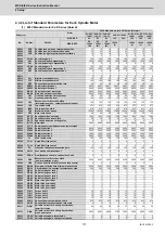
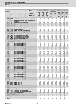
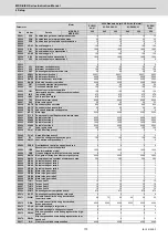
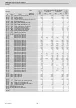
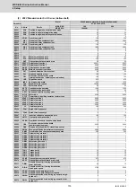
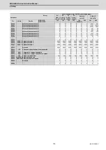
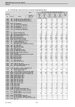
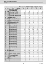
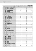
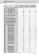
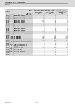
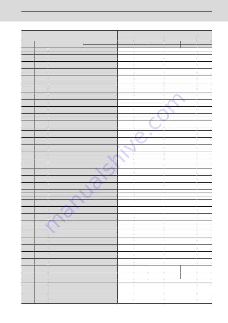
200V Standard motor SJ-D Series (Normal)
SJ-D15/
80-01
SJ-D18.5/80-01
SJ-D22/80-01
SJ-D26/
80-01
No.
Abbrev.
Details
MDS-E-SP-
200
240
320
240
320
320
MDS-E-SP2-
-
-
-
-
-
-
SP001
PGV
Position loop gain non-interpolation mode
15
15
15
15
SP002
PGN
Position loop gain interpolation mode
33
33
33
33
SP003
PGS
Position loop gain spindle synchronization
15
15
15
15
SP004
0
0
0
0
SP005
VGN1
Speed loop gain 1
150
150
150
150
SP006
VIA1
Speed loop lead compensation 1
1900
1900
1900
1900
SP007
VIL1
Speed loop delay compensation 1
0
0
0
0
SP008
VGN2
Speed loop gain 2
150
150
150
150
SP009
VIA2
Speed loop lead compensation 2
1900
1900
1900
1900
SP010
VIL2
Speed loop delay compensation 2
0
0
0
0
:
:
:
:
:
SP013
0
0
0
0
SP014
PY1
Minimum excitation rate 1
50
50
50
50
SP015
PY2
Minimum excitation rate 2
100
100
100
100
SP016
DDT
Phase alignment deceleration rate
20
20
20
20
SP017
SPEC1 Spindle specification 1
000C
000C
000C
000C
SP018
SPEC2 Spindle specification 2
0000
0000
0000
0000
SP019
RNG1
Sub side encoder resolution
2000
2000
2000
2000
SP020
RNG2
Main side encoder resolution
2000
2000
2000
2000
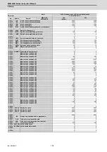
SP021
OLT
Overload detection time constant
60
60
60
60
SP022
OLL
Overload detection level
120
120
120
120
SP023
OD1
Excessive error detection width
(interpolation mode - spindle synchronization)
120
120
120
120
SP024
INP
In-position width
875
875
875
875
SP025
INP2
2nd in-position width
875
875
875
875
SP026
TSP
Maximum motor speed
8000
8000
8000
8000
SP027
ZSP
Motor zero speed
25
25
25
25
SP028
SDTS
Speed detection set value
800
800
800
800
SP029
SDTR
Speed detection reset width
30
30
30
30
SP030
SDT2
2nd speed detection setting value
0
0
0
0
SP031
MTYP
Motor type
2200
2200
2200
2200
SP032
PTYP
Power supply type/ Regenerative resistor type
-
-
-
-
SP033
SFNC1 Spindle function 1
0000
0000
0000
0000
SP034
SFNC2 Spindle function 2
0000
0000
0000
0000
SP035
SFNC3 Spindle function 3
1600
1600
1600
1600
SP036
SFNC4 Spindle function 4
0000
0000
0000
0000
SP037
JL
Load inertia scale
100
100
100
100
SP038
FHz1
Notch filter frequency 1
0
0
0
0
:
:
:
:
:
SP046
FHz2
Notch filter frequency 2
0
0
0
0
SP047
EC
Inductive voltage compensation gain
100
100
100
100
SP048
LMC1
Lost motion compensation 1
0
0
0
0
:
:
:
:
:
SP052
DFBN
Dual feedback control non-sensitive band
0
0
0
0
SP053
ODS
Excessive error detection width
(non-interpolation mode)
1600
1600
1600
1600
SP054
ORE
Overrun detection width in closed loop control
0
0
0
0
SP055
EMGx
Max. gate off delay time after emergency stop
5000
5000
5000
5000
SP056
EMGt
Deceleration time constant at emergency stop
300
300
300
300
SP057
GRA1
Spindle side gear ratio 1
1
1
1
1
SP058
GRA2
Spindle side gear ratio 2
1
1
1
1
SP059
GRA3
Spindle side gear ratio 3
1
1
1
1
SP060
GRA4
Spindle side gear ratio 4
1
1
1
1
SP061
GRB1
Motor side gear ratio 1
1
1
1
1
SP062
GRB2
Motor side gear ratio 2
1
1
1
1
SP063
GRB3
Motor side gear ratio 3
1
1
1
1
SP064
GRB4
Motor side gear ratio 4
1
1
1
1
SP065
TLM1
Torque limit 1
10
10
10
10
SP066
TLM2
Torque limit 2
10
10
10
10
SP067
TLM3
Torque limit 3
10
10
10
10
SP068
TLM4
Torque limit 4
10
10
10
10
SP069
PCMP
Phase alignment completion width
875
875
875
875
SP070
KDDT
Phase alignment deceleration rate scale
0
0
0
0
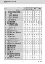
SP071
DIQM
Variable current limit during deceleration,
lower limit value
60
75
55
60
55
55
SP072
DIQN
Variable current limit during deceleration,
break point speed
4900
6000
4500
5000
4500
4500
SP073
VGVN
Variable speed gain target value
0
0
0
0
SP074
VGVS
Variable speed gain change start speed
0
0
0
0
SP075
DWSH
Slip compensation scale during regeneration high-
speed coil
0
0
0
0
SP076
DWSL
Slip compensation scale during regeneration low-
speed coil
0
0
0
0
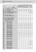
SP077
IQA
Q axis current lead compensation
4096
4096
4096
4096
Содержание MDS-E
Страница 1: ......
Страница 3: ......
Страница 15: ......
Страница 17: ......
Страница 19: ......
Страница 21: ......
Страница 31: ......
Страница 32: ...1 IB 1501229 F 1 Installation ...
Страница 76: ...45 IB 1501229 F 2 Wiring and Connection ...
Страница 132: ...101 IB 1501229 F 3 Safety Function ...
Страница 142: ...111 IB 1501229 F 4 Setup ...
Страница 277: ...MDS E EH Series Instruction Manual 4 Setup 246 IB 1501229 F ...
Страница 278: ...247 IB 1501229 F 5 Servo Adjustment ...
Страница 351: ...MDS E EH Series Instruction Manual 5 Servo Adjustment 320 IB 1501229 F ...
Страница 352: ...321 IB 1501229 F 6 Spindle Adjustment ...
Страница 404: ...373 IB 1501229 F 7 Troubleshooting ...
Страница 455: ...MDS E EH Series Instruction Manual 7 Troubleshooting 424 IB 1501229 F ...
Страница 456: ...425 IB 1501229 F 8 Maintenance ...
Страница 475: ...MDS E EH Series Instruction Manual 8 Maintenance 444 IB 1501229 F ...
Страница 476: ...445 IB 1501229 F 9 Power Backup System ...
Страница 494: ...463 IB 1501229 F 10 Appx 1 Cable and Connector Assembly ...
Страница 504: ...473 IB 1501229 F 11 Appx 2 D A Output Specifications for Drive Unit ...
Страница 513: ...MDS E EH Series Instruction Manual 11 Appx 2 D A Output Specifications for Drive Unit 482 IB 1501229 F ...
Страница 514: ...483 IB 1501229 F 12 Appx 3 Protection Function ...
Страница 523: ...MDS E EH Series Instruction Manual 12 Appx 3 Protection Function 492 IB 1501229 F ...
Страница 524: ...493 IB 1501229 F 13 Appx 4 Compliance to EC Directives ...
Страница 528: ...497 IB 1501229 F 14 Appx 5 EMC Installation Guidelines ...
Страница 540: ...509 IB 1501229 F 15 Appx 6 Higher Harmonic Suppression Measure Guidelines ...
Страница 545: ...MDS E EH Series Instruction Manual 15 Appx 6 Higher Harmonic Suppression Measure Guidelines 514 IB 1501229 F ...
Страница 550: ......
Страница 554: ......

