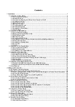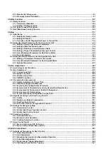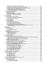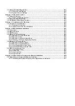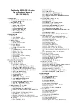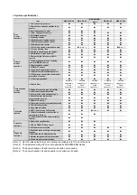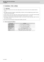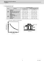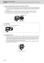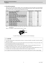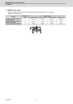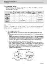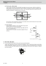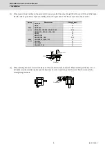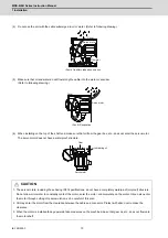
4.3.4 Installation of Tool Spindle Motor
4.4 Drive Unit
4.4.1 Environmental Conditions
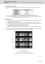
4.4.2 Heating Value
5 Dedicated Options
5.1 Servo Options
5.1.1 Dynamic Brake Unit (MDS-D-DBU)
5.1.2 Battery Option (MDS-BAT6V1SET, MDSBTBOX-
LR2060)
5.1.3 Ball Screw Side Encoder (OSA405ET2AS,
OSA676ET2AS)
5.1.4 Machine Side Encoder
5.2 Spindle Options
5.2.1 Spindle Side ABZ Pulse Output Encoder (OSE-
1024 Series)
5.2.2 Spindle Side PLG Serial Output Encoder
(TS5690, MU1606 Series)
5.2.3 Spindle Side Accuracy Serial Output Encoder
(Other Manufacturer's Product)
5.3 Encoder Interface Unit
5.3.1 Serial Output Interface Unit for ABZ Analog En-
coder MDS-EX-HR
5.3.2 Serial Signal Division Unit MDS-B-SD
5.3.3 Pulse Output Interface Unit for ABZ Analog En-
coder IBV Series
(Other Manufacturer's Product)
5.3.4 Serial Output Interface Unit for ABZ Analog En-
coder EIB192M
(Other Manufacturer's Product)
5.3.5 Serial Output Interface Unit for ABZ Analog En-
coder EIB392M
(Other Manufacturer's Product)
5.3.6 Serial Output Interface Unit for ABZ Analog En-
coder ADB-K70M
(Other Manufacturer's Product)
5.4 Drive Unit Option
5.4.1 DC Connection Bar
5.4.2 Side Protection Cover
5.4.3 Power Backup Unit (MDS-D/DH-PFU)
5.4.4 Regenerative Resistors for Power Backup Unit
(R-UNIT-6,7)
5.4.5 Capacitor Unit for Power Backup Unit (MDS-D/
DH-CU)
5.5 Cables and Connectors
5.5.1 Cable Connection Diagram
5.5.2 List of Cables and Connectors
5.5.3 Optical Communication Cable Specifications
6 Specifications of Peripheral Devices
6.1 Selection of Wire
6.1.1 Wire Selection Standards for Each Product
6.1.2 Example of Wires by Unit
6.2 Selection of Circuit Protector and Contactor
6.2.1 Selection of Circuit Protector
6.2.2 Selection of Contactor
6.3 Selection of Earth Leakage Breaker
6.4 Branch-circuit Protection (for Control Power Supply)
6.4.1 Circuit Protector
6.4.2 Fuse Protection
6.5 Noise Filter
6.6 Surge Absorber
6.7 Relay
6.8 Selection of Link Connection
6.8.1 Connection of L11 and L21 Link
6.8.2 Connection of L+ and L- Link
7 Selection
7.1 Selection of the Servo Motor
7.1.1 Outline
7.1.2 Selection of Servo Motor Capacity
7.1.3 Motor Shaft Conversion Load Torque
7.1.4 Expressions for Load Inertia Calculation
7.2 Selection of the Spindle Motor
7.3 Selection of the Power Supply Unit
7.3.1 Calculation of Spindle Output
7.3.2 Calculation of Servo Motor Output
7.3.3 Selection of the Power Supply Unit
7.3.4 Required Capacity of Power Supply
7.3.5 Example for Power Supply Unit and Power Sup-
ply Facility Capacity
7.3.6 Selection of Regenerative Resistor for Power
Backup Unit (R-UNIT-6,7) and
Capacitor Unit for Power Backup Unit (MDS-D/DH-
CU)
8 Appx. 1: Cable and Connector Specifications
8.1 Selection of Cable
8.1.1 Cable Wire and Assembly
8.2 Cable Connection Diagram
8.2.1 Battery Cable
8.2.2 Power Supply Communication Cable and Con-
nector
8.2.3 STO Cable
8.2.4 Servo Encoder Cable
8.2.5 Brake Cable and Connector
8.2.6 Spindle Encoder Cable
8.3 Main Circuit Cable Connection Diagram
8.4 Connector Outline Dimension Drawings
8.4.1 Connector for Drive Unit
8.4.2 Connector for Servo
8.4.3 Connector for Spindle
8.4.4 Power Backup Unit Connector
9 Appx. 2: Restrictions for Lithium Batteries
9.1 Restriction for Packing
9.1.1 Target Products
9.1.2 Handling by User
9.1.3 Reference
9.2 Products Information Data Sheet (ER Battery)
9.3 Forbiddance of Transporting Lithium Battery by Pas-
senger Aircraft Provided in the Code of Federal Regulation
9.4 California Code of Regulation "Best Management Prac-
tices for Perchlorate Materials"
9.5 Restriction Related to EU Battery Directive
9.5.1 Important Notes
9.5.2 Information for End-user
For outline dimension drawings, refer to "DRIVE SYSTEM DATA BOOK" (IB-1501252(ENG)).
Содержание MDS-E
Страница 1: ......
Страница 3: ......
Страница 15: ......
Страница 17: ......
Страница 19: ......
Страница 21: ......
Страница 31: ......
Страница 32: ...1 IB 1501229 F 1 Installation ...
Страница 76: ...45 IB 1501229 F 2 Wiring and Connection ...
Страница 132: ...101 IB 1501229 F 3 Safety Function ...
Страница 142: ...111 IB 1501229 F 4 Setup ...
Страница 277: ...MDS E EH Series Instruction Manual 4 Setup 246 IB 1501229 F ...
Страница 278: ...247 IB 1501229 F 5 Servo Adjustment ...
Страница 351: ...MDS E EH Series Instruction Manual 5 Servo Adjustment 320 IB 1501229 F ...
Страница 352: ...321 IB 1501229 F 6 Spindle Adjustment ...
Страница 404: ...373 IB 1501229 F 7 Troubleshooting ...
Страница 455: ...MDS E EH Series Instruction Manual 7 Troubleshooting 424 IB 1501229 F ...
Страница 456: ...425 IB 1501229 F 8 Maintenance ...
Страница 475: ...MDS E EH Series Instruction Manual 8 Maintenance 444 IB 1501229 F ...
Страница 476: ...445 IB 1501229 F 9 Power Backup System ...
Страница 494: ...463 IB 1501229 F 10 Appx 1 Cable and Connector Assembly ...
Страница 504: ...473 IB 1501229 F 11 Appx 2 D A Output Specifications for Drive Unit ...
Страница 513: ...MDS E EH Series Instruction Manual 11 Appx 2 D A Output Specifications for Drive Unit 482 IB 1501229 F ...
Страница 514: ...483 IB 1501229 F 12 Appx 3 Protection Function ...
Страница 523: ...MDS E EH Series Instruction Manual 12 Appx 3 Protection Function 492 IB 1501229 F ...
Страница 524: ...493 IB 1501229 F 13 Appx 4 Compliance to EC Directives ...
Страница 528: ...497 IB 1501229 F 14 Appx 5 EMC Installation Guidelines ...
Страница 540: ...509 IB 1501229 F 15 Appx 6 Higher Harmonic Suppression Measure Guidelines ...
Страница 545: ...MDS E EH Series Instruction Manual 15 Appx 6 Higher Harmonic Suppression Measure Guidelines 514 IB 1501229 F ...
Страница 550: ......
Страница 554: ......

