


MDS-E/EH Series Instruction Manual
14 Appx. 5: EMC Installation Guidelines
500
IB-1501229-F
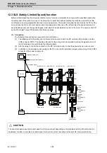
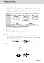
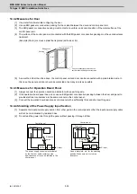
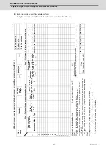
14.4.2 Measures for Door
[1] Use metal for all materials configuring the door.
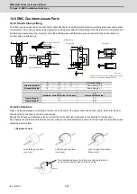
[2] Use an EMI gasket or conductive packing for the contact between the door and control panel unit.
[3] The EMI gasket or conductive packing must contact at a uniform and correct position of the metal surface of the
control panel unit.
[4] The surface of the control panel unit contacted with the EMI gasket or conductive packing must have conductance
treatment.
(Example) Weld (or screw) a plate that is plated (with nickel, tin).
[5] As a method other than the above, the control panel unit and door can be connected with a plain braided wire. In
this case, the panel and door should be contacted at as many points as possible.
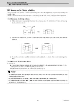
14.4.3 Measures for Operation Board Panel
[1] Always connect the operation board and indicator with an earthing wire.
[2] If the operation board panel has a door, use an EMI gasket or conductive packing between the door and panel to
provide electrical conductance in the same manner as the control panel.
[3] Connect the operation board panel and control panel with a sufficiently thick and short earthing wire.
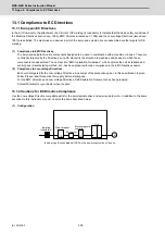
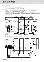
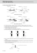
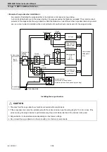
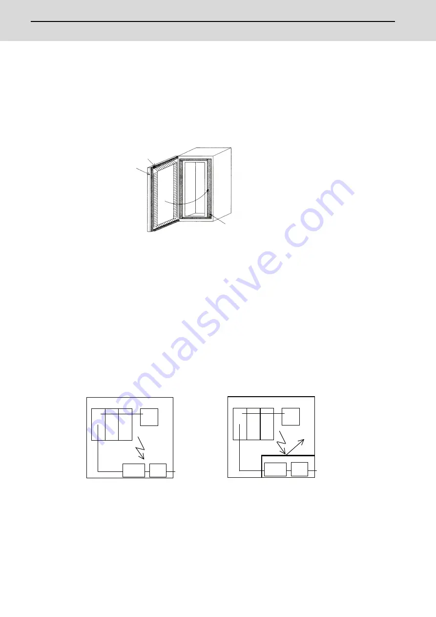
14.4.4 Shielding of the Power Supply Input Section
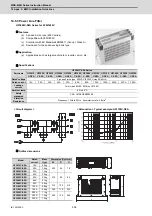
[1] Separate the input power supply section from other parts in the control panel so that the input power supply cable
will not be contaminated by radiated noise.
[2] Do not lead the power line through the panel without passing it through a filter.
EMI gasket
Packing
Control panel
Door
Carry out conductance treatment on
sections that the EMI gasket contacts.
Control panel
Control panel
Drive unit
Drive unit
Radiated
noise
Radiated
noise
AC input
AC input
Breaker
Breaker
Power
line filter
Power
line filter
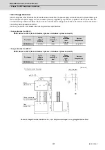
Shielding
plate
The power supply line noise is eliminated
by the filter, but cable contains noise
again because of the noise radiated in the
control panel.
Use a metal plate, etc., for the shielding
partition. Make sure not to create a
clearance.
Содержание MDS-E
Страница 1: ......
Страница 3: ......
Страница 15: ......
Страница 17: ......
Страница 19: ......
Страница 21: ......
Страница 31: ......
Страница 32: ...1 IB 1501229 F 1 Installation ...
Страница 76: ...45 IB 1501229 F 2 Wiring and Connection ...
Страница 132: ...101 IB 1501229 F 3 Safety Function ...
Страница 142: ...111 IB 1501229 F 4 Setup ...
Страница 277: ...MDS E EH Series Instruction Manual 4 Setup 246 IB 1501229 F ...
Страница 278: ...247 IB 1501229 F 5 Servo Adjustment ...
Страница 351: ...MDS E EH Series Instruction Manual 5 Servo Adjustment 320 IB 1501229 F ...
Страница 352: ...321 IB 1501229 F 6 Spindle Adjustment ...
Страница 404: ...373 IB 1501229 F 7 Troubleshooting ...
Страница 455: ...MDS E EH Series Instruction Manual 7 Troubleshooting 424 IB 1501229 F ...
Страница 456: ...425 IB 1501229 F 8 Maintenance ...
Страница 475: ...MDS E EH Series Instruction Manual 8 Maintenance 444 IB 1501229 F ...
Страница 476: ...445 IB 1501229 F 9 Power Backup System ...
Страница 494: ...463 IB 1501229 F 10 Appx 1 Cable and Connector Assembly ...
Страница 504: ...473 IB 1501229 F 11 Appx 2 D A Output Specifications for Drive Unit ...
Страница 513: ...MDS E EH Series Instruction Manual 11 Appx 2 D A Output Specifications for Drive Unit 482 IB 1501229 F ...
Страница 514: ...483 IB 1501229 F 12 Appx 3 Protection Function ...
Страница 523: ...MDS E EH Series Instruction Manual 12 Appx 3 Protection Function 492 IB 1501229 F ...
Страница 524: ...493 IB 1501229 F 13 Appx 4 Compliance to EC Directives ...
Страница 528: ...497 IB 1501229 F 14 Appx 5 EMC Installation Guidelines ...
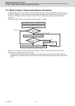
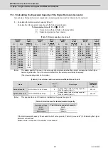
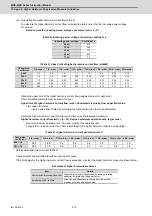
Страница 540: ...509 IB 1501229 F 15 Appx 6 Higher Harmonic Suppression Measure Guidelines ...
Страница 545: ...MDS E EH Series Instruction Manual 15 Appx 6 Higher Harmonic Suppression Measure Guidelines 514 IB 1501229 F ...
Страница 550: ......
Страница 554: ......


