(2) Wiring
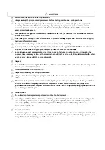
Correctly and securely perform the wiring. Failure to do so could lead to abnormal operation of the motor.
Do not install a condensing capacitor, surge absorber or radio noise filter on the output side of the drive
unit.
Correctly connect the output side of the drive unit (terminals U, V, W). Failure to do so could lead to
abnormal operation of the motor.
When using a power regenerative power supply unit, always install an AC reactor for each power supply
unit.
In the main circuit power supply side of the unit, always install an appropriate circuit protector or contactor
for each unit. Circuit protector or contactor cannot be shared by several units.
Always connect the motor to the drive unit's output terminals (U, V, W).
Do not directly connect a commercial power supply to the servo motor. Failure to observe this could result
in a fault.
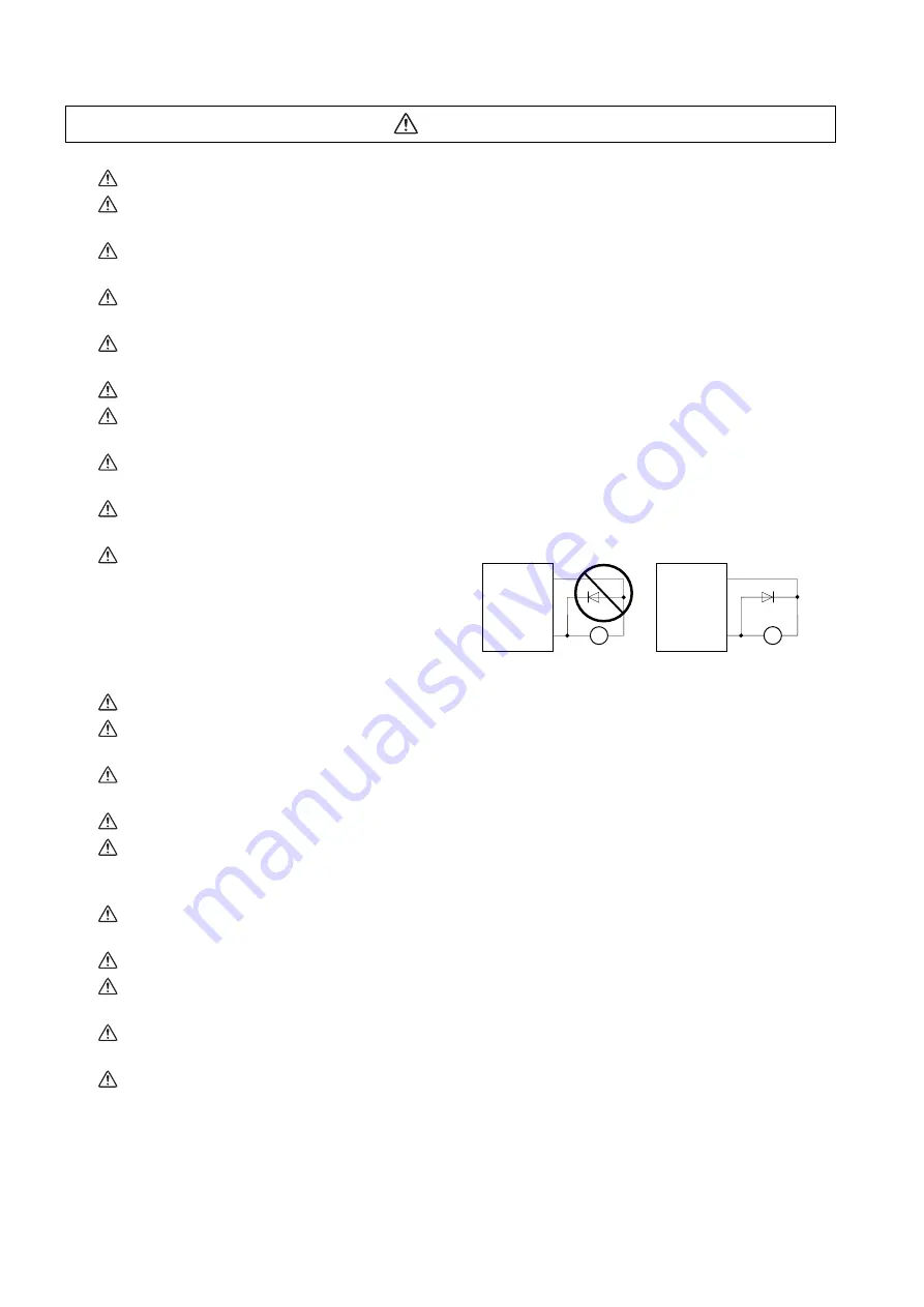
When using an inductive load such as a relay, always connect a diode as a noise measure parallel to the
load.
When using a capacitance load such as a lamp, always connect a protective resistor as a noise measure
serial to the load.
Do not reverse the direction of a diode which
connect to a DC relay for the control output
signals such as contractor and motor brake
output, etc. to suppress a surge. Connecting it
backwards could cause the drive unit to
malfunction so that signals are not output, and
emergency stop and other safety circuits are inoperable.
Do not connect/disconnect the cables connected between the units while the power is ON.
Securely tighten the cable connector fixing screw or fixing mechanism. An insecure fixing could cause the
cable to fall off while the power is ON.
When using a shielded cable instructed in the instruction manual, always ground the cable with a cable
clamp, etc. (Refer to "EMC Installation Guidelines")
Always separate the signals wires from the power line.
Use wires and cables that have a wire diameter, heat resistance and flexibility that conforms to the system.
(3) Trial operation and adjustment
Check and adjust each program and parameter before starting operation. Failure to do so could lead to
unforeseen operation of the machine.
Do not make remarkable adjustments and changes of parameter as the operation could become unstable.
The usable motor and unit combination is predetermined. Always check the combinations and parameters
before starting trial operation.
The direct-drive motor and linear servo motor do not have a stopping device such as magnetic brakes.
Install a stopping device on the machine side.
When using the linear servo motor for an unbalance axis, adjust the unbalance weight to 0 by installing an
air cylinder, etc. on the machine side. The unbalance weight disables the initial magnetic pole adjustment.
CAUTION
RA
24G
RA
24G
Servo drive unit
Servo drive unit
Control output
signal
Control output
signal
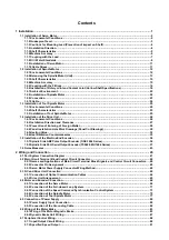
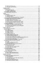
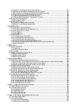
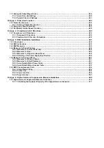
Содержание MDS-E
Страница 1: ......
Страница 3: ......
Страница 15: ......
Страница 17: ......
Страница 19: ......
Страница 21: ......
Страница 31: ......
Страница 32: ...1 IB 1501229 F 1 Installation ...
Страница 76: ...45 IB 1501229 F 2 Wiring and Connection ...
Страница 132: ...101 IB 1501229 F 3 Safety Function ...
Страница 142: ...111 IB 1501229 F 4 Setup ...
Страница 277: ...MDS E EH Series Instruction Manual 4 Setup 246 IB 1501229 F ...
Страница 278: ...247 IB 1501229 F 5 Servo Adjustment ...
Страница 351: ...MDS E EH Series Instruction Manual 5 Servo Adjustment 320 IB 1501229 F ...
Страница 352: ...321 IB 1501229 F 6 Spindle Adjustment ...
Страница 404: ...373 IB 1501229 F 7 Troubleshooting ...
Страница 455: ...MDS E EH Series Instruction Manual 7 Troubleshooting 424 IB 1501229 F ...
Страница 456: ...425 IB 1501229 F 8 Maintenance ...
Страница 475: ...MDS E EH Series Instruction Manual 8 Maintenance 444 IB 1501229 F ...
Страница 476: ...445 IB 1501229 F 9 Power Backup System ...
Страница 494: ...463 IB 1501229 F 10 Appx 1 Cable and Connector Assembly ...
Страница 504: ...473 IB 1501229 F 11 Appx 2 D A Output Specifications for Drive Unit ...
Страница 513: ...MDS E EH Series Instruction Manual 11 Appx 2 D A Output Specifications for Drive Unit 482 IB 1501229 F ...
Страница 514: ...483 IB 1501229 F 12 Appx 3 Protection Function ...
Страница 523: ...MDS E EH Series Instruction Manual 12 Appx 3 Protection Function 492 IB 1501229 F ...
Страница 524: ...493 IB 1501229 F 13 Appx 4 Compliance to EC Directives ...
Страница 528: ...497 IB 1501229 F 14 Appx 5 EMC Installation Guidelines ...
Страница 540: ...509 IB 1501229 F 15 Appx 6 Higher Harmonic Suppression Measure Guidelines ...
Страница 545: ...MDS E EH Series Instruction Manual 15 Appx 6 Higher Harmonic Suppression Measure Guidelines 514 IB 1501229 F ...
Страница 550: ......
Страница 554: ......


