5-6 Image Optimization
Focus
Description
Refers to adjusting the focus of the ultrasonic beams, using the
symbols
which are displayed to the right of the image.
Operations
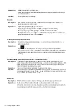
Adjust the focus number through [Focus Number] on the menu.
Tap [-] or [+] to change the value slightly or drag the control directly.
Drag
on the right part of the image area to change the focus position.
In B mode, the available focus number can be switched between 1-4.
Effects
The area that is focused will be of a higher contrast and resolution.
Impacts
The greater the number of focal zones, the slower the frame rate.
Image Adjustment
Description
More information can be obtained without moving the probe or changing the
sampling position.
FOV (Field
of View)
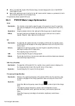
Adjust through [FOV Size (%)] on the menu.
Tap [-] or [+] to change the value slightly or drag the control directly.
You can get a much larger field of view when selecting a larger FOV.
The frame rate decreases when using a larger FOV.
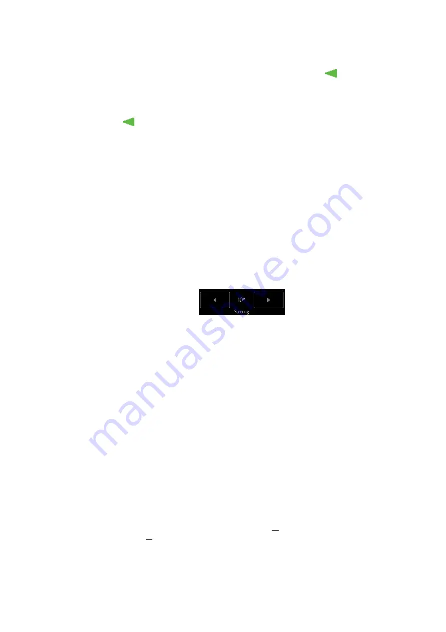
B Steer
Steer the probe by tapping buttons on the bottom of the image area.
ExFOV
(Extended
FOV)
Adjust through [ExFOV] on the menu. Off represents no ExFOV effect.
For linear probes, the ExFOV function displays as trapezoid imaging.
For convex probes, the ExFOV function displays as extending the scanning
angle.
Impacts
The FOV range is available only for convex and phased probes.
The ExFOV function is available only for convex and phased probes.
When ExFOV function is turned on, [FOV Size (%)] cannot be changed.
The B Steer function is available only for linear probes.
Rotation/Invert (U/D Flip and L/R Flip)
Description
The function provides better observation for image display.
Rotation
Rotate the image using the [Rotation] control.
Images can be rotated by 0°, 90°, 180° and 270°.
Invert (U/D
Flip and L/R
Flip)
To invert the image horizontally or vertically.
Invert the image using the [L/R Flip]/[U/D Flip] control: tap [Up]/ [Down]/ [Left]/
[Right] to invert the image at different directions.
Effects
You can identify the image orientation using the “m” mark on the screen. By
default, the “m” mark is located in the top-left corner of the image.
Содержание TE5
Страница 1: ...TE7 TE5 Diagnostic Ultrasound System Operator s Manual Basic Volume ...
Страница 2: ......
Страница 6: ......
Страница 12: ......
Страница 24: ......
Страница 36: ......
Страница 54: ......
Страница 56: ...4 2 Exam Preparation 4 1 1 New Patient Information The Patient Info screen is shown as follows 2 1 3 ...
Страница 110: ......
Страница 115: ...Display Cine Review 6 5 6 Tap Return on the screen or tap Freeze to exit image compare ...
Страница 120: ......
Страница 124: ......
Страница 156: ......
Страница 174: ......
Страница 192: ...12 18 Setup Select Advanced and do as follows Select MAPS and do as follows ...
Страница 202: ...13 2 Probes and Biopsy C5 2s L12 4s L7 3s P4 2s L14 6s C11 3s L14 6Ns V11 3Ws P7 3Ts 7LT4s ...
Страница 203: ...Probes and Biopsy 13 3 7L4s P10 4s L20 5s P7 3s L14 5sp SC6 1s SP5 1s 6CV1s L9 3s C5 1s L11 3VNs C4 1s ...
Страница 222: ...13 22 Probes and Biopsy No Name Description 8 Grooves of the needle guided bracket Matched with the tabs of the probe ...
Страница 226: ...13 26 Probes and Biopsy NGB 034 NGB 035 ...
Страница 250: ......
Страница 272: ......
Страница 276: ...A 4 Wireless LAN Tap Add Manually create a network profile to set ...
Страница 282: ......
Страница 318: ......
Страница 322: ......
Страница 323: ...P N 046 006959 07 1 0 ...


