3-40
BOP HIPWR 091719
between 2 and 3, highlight 3. To add a segment following 3, highlight
End of Segments
. After
highlighting the segment, press
@
to insert a new segment. The parameters applicable to the
waveform type selected (see Table 3-12 for details) can then be modified as desired.
3.3.10.9
USING SEGMENTS TO BUILD A WAVEFORM
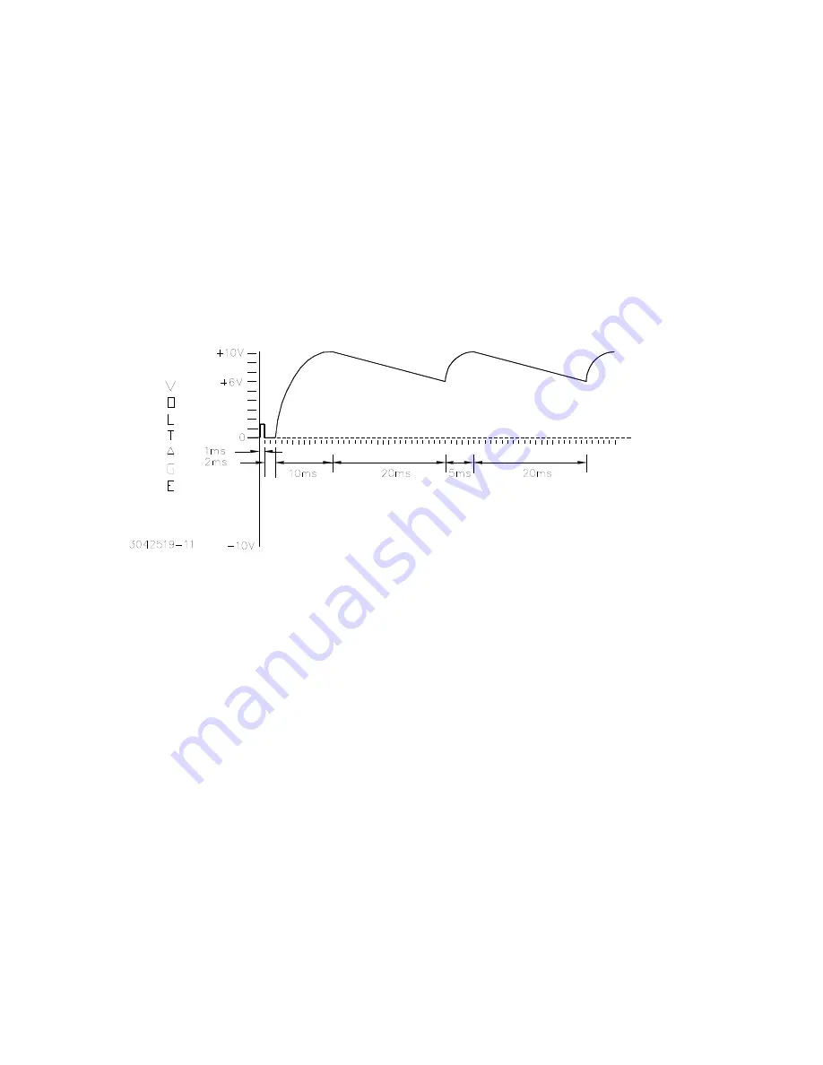
The following steps provide detailed instructions to illustrate how a complex waveform, illus-
trated in Figure 3-14, may be created by building segments. Refer to PAR. 3.2.4 for details on
changing parameters if needed.
1. After observing the precautions of PAR. 3.3.10.1, press
@
from the power-up screen to
enter the Saved Waveforms screen (Figure 3-11), highlight a waveform designated
Empty
and press
@
to create a new waveform.
FIGURE 3-14. SAMPLE WAVEFORM
2. The initial waveform settings are displayed (see Table 3-12 and Table 3-13 for parameter
details. Use
!
to modify the initial settings for the waveform. For each parameter, use
$
to save the setting.
Name
CAP CHARG
Mode
VOLTAGE
Protection
Positive
10
Negative
10
Count
0
Segment
Type
Neg Ramp
Frequency (Hz)
50
Amplitude (p-p)
4
Offset
8
When all settings are complete, press
$
to save for power-up. This step creates a repeat-
ing negative ramp starting at +10V decreasing to +6V since it is a 4V p-p signal riding on an
8V offset. The frequency of 50 Hz establishes the time duration of 20 ms for the segment.
Содержание BOP-ME 1KW
Страница 2: ......
Страница 20: ...xii BOP 1K 091719 FIGURE 1 1 HIGH POWER BOP SERIES POWER SUPPLY...
Страница 42: ......
Страница 64: ...2 22 BOP HIPWR 091719 FIGURE 2 11 PARALLEL CONFIGURATION LOCAL SENSING TYPICAL...
Страница 65: ...BOP HIPWR 091719 2 23 FIGURE 2 12 PARALLEL CONFIGURATION REMOTE SENSING TYPICAL...
Страница 76: ......
Страница 161: ...BOP HIPWR 091719 3 85 FIGURE 3 29 STATUS REPORTING STRUCTURE...
Страница 164: ......


