BOP HIPWR 091719
3-73
The
Ref Input
button allows selection of either an INTERNAL or EXTERNAL reference level to
control the main channel output. When
Ref Input
is set to EXTERNAL, the unit uses an external
reference to change the main channel, whether voltage or current. For example, in voltage
mode a ±10V reference applied to analog port pin 11 (referenced to pin 10) produces ±E
O
(rated). When
Ref Input
is set to EXTERNAL, the Output
SET
button changes to
EXTERNAL
to
indicate that the output is controlled by an external reference can not be set from the simulated
front panel. See PAR. 3.4.4.1 for more information.
The
Protection Limits
button allows selection of either INTERNAL or EXTERNAL reference
levels to control the protection limits. When
Protection Limits
is set to EXTERNAL, the unit
uses ex1V to +10V reference levels applied to analog port pins 5, 6, 13 and 14, refer-
enced to pin 12 to set the protection limits (see PAR. 3.4.5 for details). When
Protection Limits
is set to EXTERNAL, the Protection
SET
button changes to
EXTERNAL
to indicate that the pro-
tection limits are controlled by external references applied to the analog port and can not be set
from the simulated front panel.
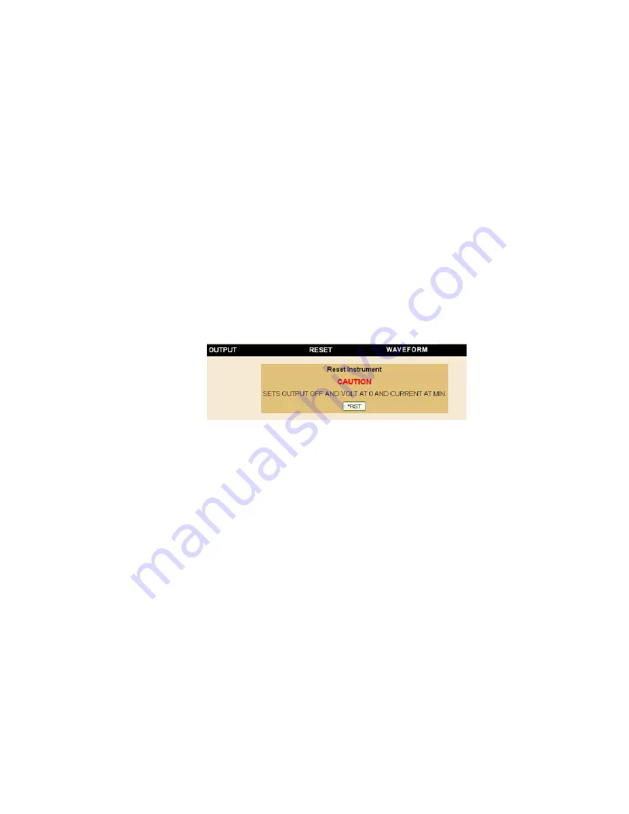
3.5.7.6.2 RESETTING THE UNIT (*RST)
Click
RESET
to open the Reset dialog box, then click
*RST
button to reset power supply to the
power on default state: setpoints to zero Volts and minimum Amperes, and output set to OFF.
*RST
also clears all LIST entries.
FIGURE 3-25. RESET DIALOG BOX
3.5.7.6.3 USING A WAVEFORM (USER-PROGRAMMED SEQUENCES)
The Waveform feature uses preconfigured LIST commands, along with up to 1000 locations
which are available for programming the BOP 1KW-ME output. These locations enable the user
to program the output using sequential steps which may be initiated by a single command. The
repeatable user-determined sequences are stored in volatile memory and are retained until
reprogrammed, the power supply is turned off, operating mode (voltage or current) is changed,
a calibration is performed, or a
LIST:CLEar
command is received.
Create the Waveform.
Click
Waveform
to open the Waveform dialog box (Figure 3-26).
Depending on the operating mode selected, either the voltage waveform or current waveform
dialog box will be displayed. Click the
MODE
button at the top of the screen to change the
mode. Each dialog box defines the values for one segment:
1. Enter
Wave Type
using the following codes:
0
Sine
1
Triangle
2
Square
3
Level
4
Positive Ramp
5
Negative Ramp
2. Enter
Wave Offset
(optional) and
Wave amplitude
in Volts or Amps, as applicable
Содержание BOP-ME 1KW
Страница 2: ......
Страница 20: ...xii BOP 1K 091719 FIGURE 1 1 HIGH POWER BOP SERIES POWER SUPPLY...
Страница 42: ......
Страница 64: ...2 22 BOP HIPWR 091719 FIGURE 2 11 PARALLEL CONFIGURATION LOCAL SENSING TYPICAL...
Страница 65: ...BOP HIPWR 091719 2 23 FIGURE 2 12 PARALLEL CONFIGURATION REMOTE SENSING TYPICAL...
Страница 76: ......
Страница 161: ...BOP HIPWR 091719 3 85 FIGURE 3 29 STATUS REPORTING STRUCTURE...
Страница 164: ......


