2-16
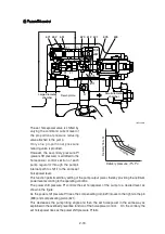
Adjustment of outer spring
Adjust it by loosening the hexagon nut
(630) and by tightening (or loosening)
the adjusting screw C (628).
Tightening the screw shifts the control
chart to the right and increases the
input horsepower as shown in the
figure. Since turning the adjusting
screw C (628) by N turns changes the
setting of the inner spring (626), return
the adjusting stem C (627) by N
Ý
A
turns at first. (A=1.48)
Adjusting value
a.
ö
Delivery pressure, (P
1
+P
2
)
Deliv
er
y flo
w
, Q
625
626
627
802
630
628
140Z92RG07
Speed
Adjustment of input horsepower
Tightening
amount of
adjusting
screw (C)
(628)
Compensa-
ting control
starting
pressure
change
amount
Input torque
change
amount
(min
-1
)
(Turn)
(kgf/cm
2
)
(kgf
Â
m)
2000
+1/4
+15.9
+2.7
Low tilting angle (low flow) command preferential function
As mentioned above, flow control and horsepower control tilting angle commands are
transmitted to the feedback lever and spool via the large-hole sections (C & F) of levers 1 and 2.
However, since sections C and F have the pins (
͚
4) protruding from the large hole (
͚
8), only
the lever lessening the tilting angle contacts the pin (897) ; the hole (
͚
8) in the lever of a larger
tilting angle command is freed without contacting the pin (897). Such a mechanical selection
method permits preference of the lower tilting angle command of the flow control and horsepower
control.
Adjustment of input horsepower
Since the regulator is of total cumulative horsepower type, adjust the adjusting screws of both
the front and rear pumps, when changing the horsepower set values. The pressure change
values by adjustment are based on two pumps pressurized at the same time, and the values will
be doubled when only one pump is loaded.
Ι
Κ
Содержание HX145 LCR
Страница 11: ...SECTION 1 GENERAL SECTION 1 GENERAL Group 1 Safety Hints 1 1 Group 2 Specifications 1 10...
Страница 204: ...4 5 MEMORANDUM HYUNDAI HEAVY INDUSTRIES CO LTD CONSTRUCTION EQUIPMENT DIV...
Страница 553: ...8 82 Insert O rings to the relief valve 30 and reassemble them to rear cover 20 This completes assembly 17 32038SM42...
Страница 627: ...8 155 125LCR8TM30 Turn casing 1 upside down and remove oil seal 3 using jig 29...
Страница 636: ...8 164 125LCR8TM61 After assembling spring 44 in order clamp plug 41 Tightening torque 5 kgf m 36 lbf ft 31...
Страница 657: ...8 185 8 185 Remove lock nut 22 and then boot 23 14 36078RL14 2507ARL10...
Страница 668: ...8 196 14 15 3 Install cover 3 to body 1 and tighten bolts 14 Torque 10 12 5 kgf m 72 3 90 4 lbf ft 7 21078DA10...


