background image

8-158

125LCR8TM37

125LCR8TM38

125LCR8TM39

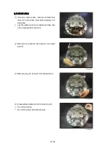
Assemble  spring  (13)  (9ea)  and  ball  guide  (14) 
in cylinder block (12) in that order.

Insert piston assembly (16) in retainer plate (15) 
and assemble them in cylinder block.
Spread hydraulic oil on piston assembly.
Take care not to damage each component.
Check  cylinder  block  and  piston  assembly  runs 
properly.

Lay  casing  down  horizontally  and  assemble 
cylinder  block  assembly  by  matching  its  spline 
with shaft.
Make sure swash plate stays in place.
Check the assembling status of cylinder block by 
pressing it. 

(7)

(8)

ö
ö
ö

(9)

ö
ö

125LCR8TM40

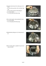
Assemble separator plate (18) (4EA) and friction 
plate (17) (3EA) alternately.

(10)

Содержание HX145 LCR

Страница 1: ...Circuit 3 5 Group 4 Single Operation 3 15 Group 5 Combined Operation 3 27 SECTION 4 ELECTRICAL SYSTEM Group 1 Component Location 4 1 Group 2 Electrical Circuit 4 3 Group 3 Electrical Component Specif...

Страница 2: ...Hydraulic and Mechanical System 6 4 Group 3 Electrical System 6 24 Group 4 Mechatronics System 6 40 SECTION 7 MAINTENANCE STANDARD Group 1 Operational Performance Test 7 1 Group 2 Major Components 7...

Страница 3: ...AULIC SYSTEM This section explains the hydraulic circuit single and combined operation SECTION 4 ELECTRICAL SYSTEM SECTION 4 ELECTRICAL SYSTEM This section explains the electrical circuit monitoring s...

Страница 4: ...ributors Get the most up to date information before you start any work Filing method Filing method See the page number on the bottom of the page File the pages in correct order Following examples show...

Страница 5: ...e so divide by 10 Move the decimal point one place to the left to convert it to 55mm Carry out the same procedure as above to convert 55mm to 2 165 inches The original value 550mm was divided by 10 so...

Страница 6: ...3 425 3 465 3 504 90 3 543 3 583 3 622 3 661 3 701 3 740 3 780 3 819 3 858 3 898 Kilogram to Pound Kilogram to Pound 1kg 2 2046lb 0 1 2 3 4 5 6 7 8 9 0 2 20 4 41 6 61 8 82 11 02 13 23 15 43 17 64 19...

Страница 7: ...455 22 719 22 983 23 247 23 511 90 23 775 24 040 24 304 24 568 24 832 25 096 25 631 25 625 25 889 26 153 Liter to U K Gallon Liter to U K Gallon 1 0 21997 U K Gal 0 1 2 3 4 5 6 7 8 9 0 0 220 0 440 0...

Страница 8: ...8 622 0 629 3 636 5 643 7 90 651 0 658 2 665 4 672 7 679 9 687 1 694 4 701 6 708 8 716 1 100 723 3 730 5 737 8 745 0 752 2 759 5 766 7 773 9 781 2 788 4 110 795 6 802 9 810 1 817 3 824 6 831 8 839 0 8...

Страница 9: ...266 90 1280 1294 1309 1323 1337 1351 1365 1380 1394 1408 100 1422 1437 1451 1465 1479 1493 1508 1522 1536 1550 110 1565 1579 1593 1607 1621 1636 1650 1664 1678 1693 120 1707 1721 1735 1749 1764 1778 1...

Страница 10: ...1 0 32 2 90 194 0 26 1 15 5 0 6 7 20 68 0 12 8 55 131 0 32 2 90 194 0 25 6 14 6 8 6 1 21 69 8 13 3 56 132 8 32 8 91 195 8 25 0 13 8 6 5 6 22 71 6 13 9 57 134 6 33 3 92 197 6 24 4 12 10 4 5 0 23 73 4 1...

Страница 11: ...SECTION 1 GENERAL SECTION 1 GENERAL Group 1 Safety Hints 1 1 Group 2 Specifications 1 10...

Страница 12: ...e excavator attach a Do Not Operate Do Not Operate tag on the right side control lever USE HANDHOLDS AND STEPS USE HANDHOLDS AND STEPS Falling is one of the major causes of personal injury When you ge...

Страница 13: ...Wear goggles or safety glasses PROTECT AGAINST NOISE PROTECT AGAINST NOISE Prolonged exposure to loud noise can cause impairment or loss of hearing Wear a suitable hearing protective device such as e...

Страница 14: ...excavator starts to move Use a signal person when moving swinging or operating the machine in congested areas Coordinate hand signals before starting the excavator OPERATE ONLY FORM OPERATOR S SEAT O...

Страница 15: ...YSTEM SAFELY Explosive release of fluids from pressurized cooling system can cause serious burns Shut off engine Only remove filler cap when cool enough to touch with bare hands HANDLE FLUIDS SAFELY A...

Страница 16: ...ide or in a well ventilated area Dispose of paint and solvent properly Remove paint before welding or heating If you sand or grind paint avoid breathing the dust Wear an approved respirator If you use...

Страница 17: ...serious injury To prevent accidents use care when working around rotating parts AVOID HIGH PRESSURE FLUIDS AVOID HIGH PRESSURE FLUIDS Escaping fluid under pressure can penetrate the skin causing serio...

Страница 18: ...e materials Pressurized lines can be accidentally cut when heat goes beyond the immediate flame area Install fire resisting guards to protect hoses or other materials PREVENT BATTERY EXPLOSIONS PREVEN...

Страница 19: ...r lime to help neutralize the acid 3 Flush your eyes with water for 10 15 minutes Get medical attention immediate ly If acid is swallowed 1 Drink large amounts of water or milk 2 Then drink milk of ma...

Страница 20: ...DO NOT pour oil into the ground down a drain or into a stream pond or lake Observe relevant environmental protection regulations when disposing of oil fuel coolant brake fluid filters batteries and ot...

Страница 21: ...rack Track roller Idler Dozer blade cylinder Dozer blade Fuel tank Hydraulic tank Main pump Tooth Turning joint Swing motor Engine Radiator Oil cooler Bucket Main control valve Battery After treatment...

Страница 22: ...cab E 2900 9 6 Ground clearance of counterweight F 930 3 1 Engine cover height G 2320 7 7 Minimum ground clearance H 440 1 5 Rear end distance I 1500 4 11 Rear end swing radius I 1500 4 11 Distance be...

Страница 23: ...900 9 6 Ground clearance of counterweight F 930 3 1 Engine cover height G 2320 7 7 Minimum ground clearance H 440 1 5 Rear end distance I 1500 4 11 Rear end swing radius I 1500 4 11 Distance between t...

Страница 24: ...ine cover height G 2320 7 7 Minimum ground clearance H 440 1 5 Rear end distance I 1500 4 11 Rear end swing radius I 1500 4 11 Distance between tumblers J 2910 9 7 Undercarriage length K 3618 11 8 Und...

Страница 25: ...ine cover height G 2320 7 7 Minimum ground clearance H 440 1 5 Rear end distance I 1500 4 11 Rear end swing radius I 1500 4 11 Distance between tumblers J 2910 9 7 Undercarriage length K 3618 11 8 Und...

Страница 26: ...und clearance of counterweight F 930 3 1 Engine cover height G 2320 7 7 Minimum ground clearance H 440 1 5 Rear end distance I 1500 4 11 Rear end swing radius I 1500 4 11 Distance between tumblers J 3...

Страница 27: ...2900 9 6 Ground clearance of counterweight F 930 3 1 Engine cover height G 2320 7 7 Minimum ground clearance H 440 1 5 Rear end distance I 1500 4 11 Rear end swing radius I 1500 4 11 Distance between...

Страница 28: ...ine cover height G 2320 7 7 Minimum ground clearance H 440 1 5 Rear end distance I 1500 4 11 Rear end swing radius I 1500 4 11 Distance between tumblers J 3090 10 2 Undercarriage length K 3798 12 6 Un...

Страница 29: ...ne cover height G 2320 7 7 Minimum ground clearance H 440 1 5 Rear end distance I 1500 4 11 Rear end swing radius I 1500 4 11 Distance between tumblers J 3090 10 2 Undercarriage length K 3798 12 6 Und...

Страница 30: ...rweight F 930 3 1 Engine cover height G 2320 7 7 Minimum ground clearance H 440 1 5 Rear end distance I 1500 4 11 Rear end swing radius I 1500 4 11 Distance between tumblers J 3090 10 2 Undercarriage...

Страница 31: ...C 3215 10 7 Superstructure width D 2500 8 2 Overall height of cab E 2900 9 6 Ground clearance of counterweight F 930 3 1 Engine cover height G 2320 7 7 Minimum ground clearance H 440 1 5 Rear end dis...

Страница 32: ...r height G 2320 7 7 Minimum ground clearance H 440 1 5 Rear end distance I 1500 4 11 Rear end swing radius I 1500 4 11 Distance between tumblers J 3090 10 2 Undercarriage length K 3798 12 6 Undercarri...

Страница 33: ...D 2500 8 2 Overall height of cab E 2900 9 6 Ground clearance of counterweight F 930 3 1 Engine cover height G 2320 7 7 Minimum ground clearance H 440 1 5 Rear end distance I 1500 4 11 Rear end swing...

Страница 34: ...ping height E 6350 mm 20 10 6470 mm 21 3 6850 mm 22 6 7230 mm 23 9 Min swing radius F 1860 mm 6 1 2030 mm 6 8 1980 mm 6 6 2260 mm 7 5 Bucket digging force SAE 87 3 94 8 kN 87 3 94 8 kN 87 3 94 8 kN 87...

Страница 35: ...29 6 9340 mm 30 8 9715 mm 31 10 Max dumping height E 6555 mm 21 6 6850 mm 22 6 7230 mm 23 9 Min swing radius F 2220 mm 7 3 2300 mm 7 7 2250 mm 7 5 Bucket digging force SAE 87 3 94 8 kN 87 3 94 8 kN 8...

Страница 36: ...777 1 3904 2 Swing bearing 228 503 Travel motor assembly 240 530 Turning joint 50 110 Track recoil spring 93 206 Idler 105 231 Carrier roller 20 45 Track roller 35 80 Sprocket 40 88 Track chain assemb...

Страница 37: ...ry or property damage Make adjustments to the rated load as necessary for non standard configurations Lift point height A Lift point radius B At max reach 1 5 m 4 9 ft 3 0 m 9 8 ft 4 5 m 14 8 ft 6 0 m...

Страница 38: ...1920 6 47 0 0ft lb 13850 12630 12210 6970 7910 4670 7100 4230 21 2 1 5m kg 5280 5280 8140 5750 5500 3120 3680 2170 5 90 4 9ft lb 11640 11640 17950 12680 12130 6880 8110 4780 19 4 3 0m kg 5850 5850 40...

Страница 39: ...60 1760 6 89 14 8ft lb 7610 7610 7120 5310 3880 3880 22 6 3 0m kg 5250 5250 4630 3660 3820 2320 1750 1630 7 37 9 8ft lb 11570 11570 10210 8070 8420 5110 3860 3590 24 2 1 5m kg 8650 6220 5600 3380 3680...

Страница 40: ...al injury or property damage Make adjustments to the rated load as necessary for non standard configurations Lift point height A Lift point radius B At max reach 3 0 m 9 8 ft 4 5 m 14 8 ft 6 0 m 19 7...

Страница 41: ...3 4 9ft lb 12570 7190 8090 4810 6370 3790 23 1 0 0m kg 5530 3120 3590 2100 2960 1750 6 86 0 0ft lb 12190 6880 7910 4630 6530 3860 22 5 1 5m kg 9130 5710 5490 3080 3570 2090 3320 1950 6 33 4 9ft lb 201...

Страница 42: ...3 0 68yd3 0 45m3 0 59yd3 915mm 36 0 1015mm 40 0 460 kg 1010 lb X 0 58m3 0 76yd3 0 50m3 0 65yd3 1000mm 39 4 1100mm 43 3 480 kg 1060 lb X 0 65m3 0 85yd3 0 55m3 0 72yd3 1105mm 43 5 1205mm 47 4 500 kg 110...

Страница 43: ...for materials with density of 1600 kg m3 2700 lb yd3 or less Applicable for materials with density of 1100 kg m3 1850 lb yd3 or less Capacity Width Weight Recommendation 4 6 m 15 1 Mono boom 4 9 m 16...

Страница 44: ...hout side cutter With side cutter 1 9 m arm 6 3 2 1 m arm 6 11 2 5 m arm 8 2 0 23 m3 0 30 yd3 0 20 m3 0 26 yd3 520 mm 20 5 620 mm 24 4 335 kg 740 lb 0 40 m3 0 52 yd3 0 35 m3 0 46 yd3 750 mm 29 5 850 m...

Страница 45: ...side cutter 1 9 m arm 6 3 2 1 m arm 6 11 2 5 m arm 8 2 0 45 m3 0 59 yd3 0 40 m3 0 52 yd3 1520 mm 59 8 410 kg 900 lb 0 55 m3 0 72 yd3 0 45 m3 0 59 yd3 1800 mm 70 9 585 kg 1290 lb Applicable for materia...

Страница 46: ...8 Operating weight kg lb 15880 35010 16110 35520 16330 36000 Ground pressure kgf cm2 psi 0 50 7 16 0 43 6 06 0 37 5 26 Overall width mm ft in 2500 8 2 2600 8 6 2700 8 10 HX145LCR Shoe width mm in 500...

Страница 47: ...d pressure Application of wider shoes than recommendations will cause unexpected problem such as bending of shoes crack of link breakage of pin loosening of shoe bolts and the other various problems 4...

Страница 48: ...in Compression ratio 16 5 1 Rated net horse power SAE J1349 116 Hp 87 kW at 1950 rpm Rated gross horse power SAE J1995 124 Hp 92 6 kW at 1950 rpm Maximum torque 54 kgf m 391 lbf ft at 1400 rpm Engine...

Страница 49: ...cement axial piston motor Capacity 71 cc rev 72 cc rev Relief pressure 285 kgf cm2 4050 psi Braking system Automatic spring applied hydraulic released Braking torque 31 3 kgf m 226 lbf ft 30 kgf m 217...

Страница 50: ...erformance Item Specification Boom cylinder Bore dia Stroke 105 1105 mm Cushion Extend only Arm cylinder Bore dia Stroke 115 1138 mm Cushion Extend and retract Bucket cylinder Bore dia Stroke 100 850...

Страница 51: ...lycol base permanent type 50 50 SAE 5W 40 SAE 75W 90 ISO VG 15 Ethyleneglycolbasepermanenttype 60 40 50 30 20 10 0 10 20 30 40 58 22 4 14 32 50 68 86 104 ISO VG 32 Using any lubricating oils other tha...

Страница 52: ...SECTION 2 STRUCTURE AND FUNCTION Group 1 Pump Device 2 1 Group 2 Main Control Valve 2 20 Group 3 Swing Device 2 47 Group 4 Travel Device 2 58 Group 5 RCV Lever 2 96 Group 6 RCV Pedal 2 103...

Страница 53: ...P1 A3 Dr2 a3 PH2 B3 A1 pump Valve block A2 pump Gear pump VIEW A A A1 A2 Hydraulic circuit B1 Dr2 PH1 PH2 Dr1 a2 PH2 PH1 145LCR2MP01 Port Port name Port size A1 A2 Delivery port SAE6000 psi 3 4 B1 Su...

Страница 54: ...shing 157 Cylinder spring 211 Shoe plate 212 Swash plate 214 Bushing 251 Support 255 Lock pin 261 Seal cover F 263 Seal cover R 271 Pump casing F 272 Pump casing R 312 Valve block 313 Valve plate R 31...

Страница 55: ...er bearing 128 Bearing spacer 262 Cover 326 Gear case 414 Hexagon socket bolt 435 Flange socket bolt 468 Plug 711 O ring 728 O ring 825 Retainer ring 826 Retainer ring 885 Spring pin 886 Pin 826 115 1...

Страница 56: ...96 VIEW C REAR VIEW C FRONT E E SECTION E E REAR 496 724 437 079 753 755 466 755 656 496 753 439 753 418 Pi Pi Pi P1 P1 P2 KR76 9N01 V FRONT KR76 9N02 V REAR A B P1 Pi 140Z92MP04 Port Port name Port s...

Страница 57: ...14 Center plug 615 Adjust plug 616 Plug 621 Compensator piston 622 Piston case 623 Compensator rod 624 Spring seat C 625 Outer spring 626 Inner spring 627 Adjust stem C 628 Adjust screw C 629 Cover C...

Страница 58: ...53 Drive gear 354 Driven gear 355 Filter 361 Front case 433 Flange socket 434 Flange socket 435 Flange socket 466 Plug 700 Ring 710 O ring 725 O ring 732 O ring 850 Snap ring 887 Pin 700 354 351 710 4...

Страница 59: ...211 swash plate support 251 lock pin 255 tilting bushing 214 tilting pin 531 and servo piston 532 The swash plate is a cylindrical part formed on the opposite side of the sliding surface of the shoe...

Страница 60: ...is driven by a prime mover electric motor engine etc it rotates the cylinder block via a spline linkage at the same time If the swash plate is tilted as in Fig previous page the pistons arranged in t...

Страница 61: ...elivery flow Q decreases as the pilot pressure Pi rises With this mechanism when the pilot pressure corresponding to the flow required for the work is commanded the pump discharges the required flow o...

Страница 62: ...pool moves to the right The movement of the spool causes the delivery pressure P1 to connect to port CL through the spool and to be admitted to the large diameter section of the servo piston The deliv...

Страница 63: ...hifts the spool to the left Port CL opens a way to the tank port as the spool moves This deprives the large diameter section of the servo piston of pressure and shifts the servo piston to the left by...

Страница 64: ...ew 924 Tightening the screw shifts the control chart to the right as shown in the figure Adjusting value Adjustment of flow control characteristic 801 924 Speed Adjustment of flow control characterist...

Страница 65: ...mps in the tandem double pump system the prime mover is automatically prevented from being overloaded irrespective of the load condition of the two pumps when horsepower control is under way Since thi...

Страница 66: ...1 the feedback lever rotates around the fulcrum of point D as lever 1 rotates and then the spool 652 is shifted to the right As the spool moves the delivery pressure P1 is admitted to the large diamet...

Страница 67: ...ulcrum of point D and then the spool 652 to move to the left As a result port CL opens a way to the tank port This causes the servo piston to move to the left and the pump s delivery rate to increase...

Страница 68: ...ow command preferential function As mentioned above flow control and horsepower control tilting angle commands are transmitted to the feedback lever and spool via the large hole sections C F of levers...

Страница 69: ...g the screw increases the flow and then the input horsepower as shown in the figure Adjusting value b Delivery pressure P1 P2 Delivery flow Q 625 626 627 802 630 628 140Z92RG08 Speed Adjustment of inp...

Страница 70: ...imum power level according to the operating condition The power shift pressure Pf controls the set horsepower of the pump to a desired level as shown in the figure As the power shift pressure Pf rises...

Страница 71: ...e maximum flow other characteristics are not changed However remember that if tightened too much the required horsepower during the maximum delivery pressure or during relieving may increase Adjustmen...

Страница 72: ...ock valve pilot port arm Arm in regen cut signal selector port Arm out pilot port Arm out confluence pilot port Bucket in pilot port Bucket out pilot port Option B pilot port Option B pilot port Optio...

Страница 73: ...Spool straight travel 4 Spool travel LH RH 6 Spool swing 7 Spool boom 1 8 Spool swing priority 9 Spool boom 2 10 Spool arm 2 11 Spool arm 1 12 Spool arm regeneration 13 Spool option B 14 Spool bucket...

Страница 74: ...k signal Pc5 Pd5 Rs C6 Pd6 Pc6 D6 DR4 P03 P1 P2 Patt P02 Pn2 Pn1 Po5 P04 DR2 Pc3 Swing priority Pa20 DR1 DR5 DR3 Pc40 BUCKET Pb21 Unlock signal Pb20 Pd40 Pd41 Pb3 Pc42 Arm crowd pilot Pc40 Pc41 Pa21 B...

Страница 75: ...pump A2 is directed to the tank through the bypass passage of spools travel left boom 1 arm 2 arm regeneration option A and bucket the negative relief valve of P1 tank passage and the tank port T1 1...

Страница 76: ...to the tank through the bypass passage of spools travel right swing boom 2 swing priority arm 1 option B and option C dozer the negative relief valve of P2 tank passage and the tank port T1 2 2 SECTIO...

Страница 77: ...port pb1 pc1 And it shifts travel right and left spools in the left direction against springs Hydraulic fluid from the pump A1 flow into the travel right spool through the bypass passage and hydraulic...

Страница 78: ...ther actuator operation during straight travel operation The other actuator operation during straight travel operation When the other actuator spool s is selected under straight travel operation the s...

Страница 79: ...boom 2 and shifts the boom 2 spool The bypass passage is shut off by the movement of the boom 2 spool and the hydraulic oil fluid from pump A1 entered boom summation passage via the P2 parallel passa...

Страница 80: ...the same time the return flow from the head side of the boom cylinder returns to the port A2 and boom holding valve And it is directed to the hydraulic oil tank through opened tank passage by movemen...

Страница 81: ...de of the holding valve through the periphery hole of check crevice of the check and the plug and the periphery hole of plug Then this pressured oil pushed the poppet to the poppet seat and the check...

Страница 82: ...ugh the periphery hole of check crevice of the check and the plug the periphery hole of the plug in side of holding valve crevice of the poppet and the poppet seat the periphery hole of the poppet sea...

Страница 83: ...red P1 parallel passage and is directed to the port A5 through the check 1 At the same time the hydraulic fluid from P1 bypass passage is directed to the port A5 through the check 2 Following this it...

Страница 84: ...t spool and the hydraulic fluid from pump A2 entered P1 parallel passage and is directed to the port B5 through the check 1 At the same time the hydraulic fluid from P1 bypass passage is directed to t...

Страница 85: ...OPERATION When combined operation mostly same as previous page but the fluid from P1 bypass passage is empty So only the fluid from P1 parallel passage is supplied to the bucket cylinder Also parallel...

Страница 86: ...D2 As the result swing motor turns and flow from the swing motor returns to the hydraulic oil tank through the port C2 swing spool and the tank passage In case of swing right operation the operation i...

Страница 87: ...ng motor Also parallel passage is installed the orifice of swing logic valve for supplying the fluid from pump A1 to the boom or the arm operation prior to the swing operation In case of the swing rig...

Страница 88: ...e and shifts arm 2 spool in the right direction The bypass passage is shut off by the movement of the arm 2 spool and the hydraulic fluid from the pump A2 flows into the arm summation passage through...

Страница 89: ...ilot pressure from RCV Then the arm regeneration spool shifts to right side and flow to tank pass increases and regeneration flow decreases Therefore pressure of arm cylinder head increases then arm r...

Страница 90: ...the movement of the arm 2 spool and some of the hydraulic fluid from pump A2 bypassed through bypass notch The rest of hydraulic fluid from pump A2 flows into the arm summation passage through P1 par...

Страница 91: ...of arm 1 side through swing priority spool and the path A and also flows into the boom 2 spool When the swing priority spool is neutral condition the passage is same as normal condition But due to shi...

Страница 92: ...ozer spool in the left direction The hydraulic fluid from the pump A1 enters the parallel passage and is direction to the head side of the dozer cylinder through port D6 The return flow from the rod s...

Страница 93: ...mp A2 The bypass passage is shut off when the shifting of one or more spools and the flow through bypass passage became zero The pressure of negative control signal becomes zero and the discharge of t...

Страница 94: ...iston A pushes open the poppet and flows to tank passage T through the plunger internal passage periphery orifice A chamber A periphery orifice B and the hole E 2 Opening the poppet causes the pressur...

Страница 95: ...ng and the plunger is seated to the socket 4 Poppet Housing P Spring Tank passage T Socket Plunger 14W92MC39 Piston B Housing P Spring Hole A Tank passage T 14W92MC40 When the power boost switch is ON...

Страница 96: ...d the socket against the housing securely 12 12 1 When the pressure at port P becomes equal to the set pressure of the spring the pressurized oil pushes open the poppet and flows to tank passage T thr...

Страница 97: ...3 The pressure at port P becomes lower than set pressure of the spring the poppet is seated by spring force Then the pressure at port P becomes equal to set pressure of the spring and the plunger is s...

Страница 98: ...hrough tank passage T When the pressure at tank passage T becomes higher than that of at port P the socket moves in the right direction Then sufficient oil passes around the socket from tank passage T...

Страница 99: ...pply port Oil level air vent port Reduction gear Reduction gear oil drain port PT 1 2 Swing motor Relief valve Hydraulic circuit AU MU MA MB DR VA VB PG SH R G 125LCR2SM21 GROUP 3 SWING DEVICE Port Po...

Страница 100: ...e casing 23 Check valve 24 Spring 25 Plug 26 O ring 27 Plug 28 O ring 29 Plug 30 O ring 31 Relief valve assy 32 Anti rotating valve assy 33 Plug 34 O ring 35 O ring 36 Time delay valve spool 37 Spring...

Страница 101: ...13 Thrust washer No 2 14 Carrier pin No 2 15 Spring pin 16 Sun gear No 2 17 Carrier No 1 18 Planetary gear No 1 19 Needle bearing No 1 20 Thrust washer No 1 21 Carrier pin No 1 22 Sun gear No 1 23 Sn...

Страница 102: ...rking on a piston This force F1 is divided as N1 thrust partial pressure and W1 radial partial pressure in case of the plate of a tilt angle W1 generates torque T W1 R1 forY Y line connected by the up...

Страница 103: ...iately before the port leading to the hydraulic oil tank to secure feed pressure required when the hydraulic motor makes a pumping action The boost pressure acts on the hydraulic motor s feed port via...

Страница 104: ...relief valves relieve high pressure at start or at stop of swing motion and can control the relief pressure in two steps high and low in order to insure smooth operation Function of relief valve Funct...

Страница 105: ...at tank pressure When hydraulic oil pressure P A1 reaches the preset force FSP of spring 4 the poppet 2 moves to the right as shown P1 A1 Fsp Pg A2 A1 P R A2 m h n g P P1 2 g 4 P1 Fsp Pg A2 A1 145WF2S...

Страница 106: ...rce FSP of spring 4 the piston 7 moves left and stop the piston 7 hits the bottom of stopper 8 When piston 7 hits the bottom of stopper 8 it stops moving to the left any further As the result the pres...

Страница 107: ...and arm in control lever are not operated Brake assembly Brake assembly Circumferential rotation of separate plate 14 is constrained by the groove located at casing 1 When housing is pressed down by...

Страница 108: ...ve 35 This pressure moves spool 5 to the leftward against the force of the spring 8 so pilot pump charged oil P3 goes to the chamber G through port PG This pressure is applied to move the parking pist...

Страница 109: ...t Then the parking piston 15 is moved lower by spring force and the return oil from the chamber G flows back to tank port At this time the brake works b Time delay valve 16 15 G 1 2 P3 5 8 SH PG 1 RCV...

Страница 110: ...eduction gear P1 Travel motor P2 T2 Hydraulic circuit R G Oil drain port PF 3 8 R G Oil inlet port PF 3 8 R G Oil check port PF 3 8 Ps VIEW Y P2 P1 RED T1 a3 T2 a2 Ps 14092TM01A GROUP 4 TRAVEL DEVICE...

Страница 111: ...2 59 14092TM02 BASIC STRUCTURE BASIC STRUCTURE 1 1 Reduction gear Travel motor Brake valve Parking brake Main control valve Main pump High low speed changeover mechanism...

Страница 112: ...in spring 30 Check spring 32 Oil seal 33 O ring 35 O ring 36 O ring 37 O ring 38 O ring 39 O ring 41 Parallel pin 42 Parallel pin 43 Socket bolt 45 Snap ring 46 O ring 47 Back up ring 48 Back up ring...

Страница 113: ...event cavitation of the hydraulic motor Relief valve function to control the brake pressure of hydraulic motor and anti cavitation valve function to prevent cavitation Opens a port which releases the...

Страница 114: ...5 four or five and generates a force F kgf P kgf cm2 A cm2 This force acts on swash plate 3 and is resolves into components F2 and F3 because swash plate 3 is fixed at an angle with the axis of drive...

Страница 115: ...port D on the passage return side of hy draulic motor which is closed by the spool groove during stoppage communicates with port B at the tank side and the return oil from the hydraulic motor runs in...

Страница 116: ...ton 409 slides to the right so as not to rise the pressure as shown in the figure Meanwhile the left hand valve 401 is pushed open by the pressurized oil in port D Therefore the pressurized oil in por...

Страница 117: ...ment of fric tion plate 15 becomes free Whereby the brake force to the cylinder in the hydraulic motor assembly is released 13 12 101 a 15 16 Stopping Stopping When the pressurized oil from the brake...

Страница 118: ...m thus leading to low speed rotation A B C A B Pilot pressure D 66 65 3 1 Y side 61 P Drain At high speed At high speed pilot pressure of 20 kgf cm2 or more When a pilot pressure is supplied from port...

Страница 119: ...gears R 117 Then planetary gears R 117 revolves inside fixed hub 105 This rotation becomes the output of 1st stage and is transmitted to carrier No 1 and sun gear 114 Similarly the revolution of plane...

Страница 120: ...ow speed changeover mechanism P1 P2 D P A B R G Hydraulic circuit D A B P VIEW X X Reduction gear Travel motor PF1 2 PF1 2 PF1 2 FILL LEVEL DRAIN P1 P2 145Z9A2TM01 Port Port name Port size A B Main po...

Страница 121: ...Cylinder block 11 Spring seat 12 Spring 13 Snap ring 14 Pin 15 Ball guide 16 Set plate 17 Piston assy 18 Steel plate 19 Friction plate 20 Brake piston 21 Ring 22 Ring 23 O ring 24 O ring 25 Valve casi...

Страница 122: ...bearing 4 Housing 5 Shim 6 Shim 7 Carrier assy 2 7 1 Carrier 2 7 2 Spring pin 2 7 3 Planetary gear 2 7 4 Washer 2 7 5 Bearing 2 7 6 Pin 2 8 Coupling 9 Sun gear 2 10 Carrier assy 1 10 1 Carrier 1 10 2...

Страница 123: ...o axial force F which is parallel with a shaft and radial force F2 which is perpendicular to the shaft By the reaction force F2 cylinder block rotate with piston and shoe while shoe 2 moves on the sho...

Страница 124: ...the traveling inertia of the excavator s heavy weight Then the motor will act as a pump and oil blocked between control valve and motor will be pressured sharply and the increased oil pressure will da...

Страница 125: ...lows into chamber 2 through orifice 2 and at this point the plunger moves to the left again when the spring is compressed by the flowed pressure oil which press the spool to the left Stage 2 When the...

Страница 126: ...ng WHEN IT STOP WHEN IT STOP RELIEF VALVE B RELIEF VALVE B When it stops or operates reversely RA port pressure is decreased and RB port pressure suddenly goes up by the inertia of the machine heavy s...

Страница 127: ...l lever traveling working pressurized oil into IN PORT flows from spool chamber through counter orifice Pressurized oil pushes counter balance spool to right Then notch of spool opens the brake line A...

Страница 128: ...and the counter balance spool returns to neutral position At the spool neutral position notch is disconnected from oil supply port A instead brake chamber oil is drained to tank through brake orifice...

Страница 129: ...eration Prevent overrun while traveling on down slope Work as a hydraulic brake when motor stops and prevent motor not to slip on slope 4 4 Brake fluid pressure way B Port OUT Port A Port IN Port Coun...

Страница 130: ...pump oil flow into cylinder block through check poppet and kidney port At that time spool notch is opened and pump oil also go through line and passes into parking brake chamber and it releases parki...

Страница 131: ...then counter balance spool returns to neutral position As the counter balance spool moves to left line is blocked parking brake line is connected to drain passage designed in the center of counter ba...

Страница 132: ...HANGEOVER EQUIPMENT Rotating speed of the motor depends on slope angle of swash plate 9 Motor rotates slow when the angle is large and rotates fast when the angle is small Low speed ow speed When pilo...

Страница 133: ...5Z9A2TM14 High speed When pilot pressure signal Pi is activated on spool 35 the spool moves to left hand end and high pressure oil from Port or is transferred to S1 which is connected to chamber A The...

Страница 134: ...ing gear a Carrier k Sun gear s Planetary pinions b 4 REDUCTION GEAR 4 REDUCTION GEAR PLANETARY GEAR MECHANISM PLANETARY GEAR MECHANISM Reduction unit slows down the rotating speed of motor and conver...

Страница 135: ...low speed changeover mechanism GROUP 4 TRAVEL DEVICE GROUP 4 TRAVEL DEVICE TYPE 3 4 TYPE 3 4 PS DR MA MB VB VA P No 39Q4 40100 38Q4 40100 Travel motor Reduction gear Ps MB VB VA MA DR Hydraulic circui...

Страница 136: ...ver 31 Main spool assy 32 Cover 33 Spring 34 Restrictor 35 Spring 36 O ring 37 Spring seat 38 Relief valve assy 39 O ring 40 Spool 41 Plug 42 Spring seat 43 Parallel pin 44 Spring 45 Connector 46 O ri...

Страница 137: ...istons which are on one side of the lineY Y that connects upper and lower dead points and produces force F1 F1 P A P pressure A area of piston section The swash plate 11 with inclined angle of divides...

Страница 138: ...is generated by the friction between the separated plates 18 inserted into the casing 1 and friction plates 17 coupled to cylinder block 12 by the outer splines When no pressure is activated on the p...

Страница 139: ...leased to the hydraulic tank through restrictor 55 Here nine pistons are there and they equally spaced on the swash plate 11 The force that summed up those of pistons comes to almost the center of the...

Страница 140: ...e setting pressure and supports the spring seat 38 3 that is inserted in the sleeve 38 4 piston 38 5 that reduce the shock 1 1 38 1 38 12 38 2 38 13 38 7 38 6 38 9 38 11 38 10 38 8 38 4 38 3 38 5 125L...

Страница 141: ...applied to the effective diameter of poppet 38 8 which seats on the poppet seat 38 9 and at the same time is delivered via small hole to the spring seat 38 3 located inside the sleeve 38 4 and the sea...

Страница 142: ...holding accelerating stopping and counterbalance operations See page 2 66 2 Operation Check valve Check valve built in the spool This valve is located in the oil supplying passage to hydraulic motor...

Страница 143: ...the rotation of the motor is mechanically prevented If external torque is exerted on the motor shaft the motor would not rotate as usual by this negative parking brake In case the brake should be rel...

Страница 144: ...the pressure supplied from pump At the same time the pressure of pilot chamber increases to push and move the spool 31 leftwards overcoming the spring 33 force Thus the return line from MB to VB open...

Страница 145: ...he passage from MA to VA is closed Owing to the inertia force of the load the hydraulic motor tends to continue the rotation Here the motor functions as a pump and forwards the oil to MB port but the...

Страница 146: ...becomes smaller and the pressure on MA side rises due to increased resistance in the passage and the motor receives hydraulic braking effect If the motor rotates slower than that matched to the volum...

Страница 147: ...d S1 S2 K1 K2 Ring gear a Carrier k Sun gear s Planetary pinions b REDUCTION GEAR REDUCTION GEAR Reduction unit slows down the rotating speed of motor and converts motor torque to strong rotating forc...

Страница 148: ...M3 M10 5 A A 19 Single operation 25 Simultaneous operation 2 3 T 1 P 4 RH 6 5 6 TYPE M5 8 7 Null Null Switches Switches Type No LH RH M1 M3 M10 5 One touch decel Horn 6 Power boost Breaker M5 5 One t...

Страница 149: ...Power boost Breaker M6 5 One touch decel Horn 6 Power boost Null 7 CCW rotation Close 8 CW rotation Open Pilot ports Pilot ports Port LH RH Port size P Pilot oil inlet port Pilot oil inlet port PF 3...

Страница 150: ...e based on the type M1 The construction of the pilot valve is shown in the attached cross section drawing The casing has vertical holes in which reducing valves are assembled The pressure reducing sec...

Страница 151: ...AJOR SECTIONS Item numbers are based on the type M1 Item numbers are based on the type M1 The functions of the spool 3 are to receive the supply oil pressure from the hydraulic pump at its port P and...

Страница 152: ...he hydraulic circuit diagram shown below and the attached operation explanation drawing The diagram shown below is the typical application example of the pilot valve 1 Pilot valve 2 Pilot pump 3 Main...

Страница 153: ...ool is pushed up by the spring 7 to the position of port 1 3 in the operation explanation drawing Then since the output port is connected to tank port T only the output port pressure becomes equal to...

Страница 154: ...eases higher than the set pressure port P is disconnected from port 1 and port T is con nected with port 1 If it decreases lower than the set pressure port P is connected with port 1 and port T is dis...

Страница 155: ...ure and the oil outlet port T tank In addition the secondary pressure is taken out through ports 1 2 3 and 4 provided at the bottom face GROUP 6 RCV PEDAL GROUP 6 RCV PEDAL Port P T 1 2 3 4 Port size...

Страница 156: ...od 14 by the return spring When the push rod is pushed down by tilting pedal the spring seat comes down simultaneously and changes setting of the secondary pressure spring 1 Body 1 2 Body 2 3 Plug 4 P...

Страница 157: ...TIONS OF MAJOR SECTIONS FUNCTIONS OF MAJOR SECTIONS The functions of the spool 8 are to receive the supply oil pressure from the hydraulic pump at its port P and to change over oil paths to determine...

Страница 158: ...basis of the hydraulic circuit diagram shown below and the attached operation explanation drawing The diagram shown below is the typical application example of the pilot valve 3 3 1 Pilot valve 2 Pil...

Страница 159: ...6 that determines the output pressure of the pilot valve is not applied to the spool 8 Therefore the spool is pushed up by the spring 10 to the position of 1 and port 2 Then since the output port is c...

Страница 160: ...1 increases higher than the set pressure port P is disconnected from port 1 and port T is connected with port 1 If it decreases lower than the set pressure port P is connected with port 1 and port T i...

Страница 161: ...SECTION 3 HYDRAULIC SYSTEM SECTION 3 HYDRAULIC SYSTEM Group 1 Hydraulic Circuit 3 1 Group 2 Main Circuit 3 2 Group 3 Pilot Circuit 3 5 Group 4 Single Operation 3 15 Group 5 Combined Operation 3 27...

Страница 162: ...2 4 6 25 D J E H 51 51 J1 J2 J3 J4 M1 M2 M3 M4 Mu MA MB B A P A B T A1 A2 A3 B1 B2 B3 T2 SWING FINE CONTROL QUICK CLAMP SWING PARKING BY FORCE P1 P2 P3 T 50 2 3 2 Pc2 25 b 25 a 25 e1 2 Pd2 3 SH 64 65...

Страница 163: ...DELIVERY CIRCUIT To cylinders To motors Main control valve To hydraulic oil tank Suction strainer Main pump To oil cooler Hydraulic oil tank GROUP 2 MAIN CIRCUIT GROUP 2 MAIN CIRCUIT The pumps receive...

Страница 164: ...nk resulting in the oil temperature being raised quickly at an appropriate level When the oil cooler is clogged the oil returns directly to the hydraulic tank through bypass check valve 1 The full flo...

Страница 165: ...drain ports provided in the respective motor casing and join with each other These oils pass through the turning joint and return to the hydraulic tank after being filtered by drain filter SWING MOTO...

Страница 166: ...gh line filter EPPR valve solenoid valve assemblies swing parking brake main control valve and safety lock solenoid valve GROUP 3 PILOT CIRCUIT GROUP 3 PILOT CIRCUIT MCV Remote control valve LH lever...

Страница 167: ...P02 MCV P0 MCV SAFETY SOLENOID VALVE Pu Pc42 Pb3 Pd41 B2 A2 Pb1 A1 B1 Pa1 T1 V3 Pd2 Pc2 D2 C2 Pc1 D1 C1 P0 DR0 Pd1 Ai B4 B5 A5 Pa5 Pb5 Pa4 Pb4 C5 D5 D4 C4 Pc41 Pc5 Pd5 Rs C6 Pd6 Pc6 D6 DR4 P03 P1 P2...

Страница 168: ...B4 B5 A5 Pa5 Pb5 Pa4 Pb4 C5 D5 D4 C4 Pc41 Pc5 Pd5 Rs C6 Pd6 Pc6 D6 DR4 P03 Patt P02 Pn2 Pn1 Po5 Puo P04 DR2 Pc3 Pa21 Pb21 Pb20 Pa20 DR1 DR5 DR3 Pc40 Pd40 PS PS Pi1 Pump Dr dr Pi2 Pump 3 1 2 4 3 1 P T...

Страница 169: ...ET CYLINDER BOOM CYLINDER TURNING JOINT TRAVEL MOTOR SWING MOTOR BOOM PRIORITY EPPR VALVE Boom speed TRAVEL STRAIGHT TRAVEL TRAVEL BOOM 1 SWING BOOM 2 ARM 1 OPTION B OPTION C DOZER ARM BUCKET ARM 2 RE...

Страница 170: ...1 Pa1 T1 V3 Pd2 Pc2 D2 C2 Pc1 D1 C1 P0 DR0 Pd1 Ai B4 B5 A5 Pa5 Pb5 Pa4 Pb4 C5 D5 D4 C4 Pc41 Pc5 Pd5 Rs C6 Pd6 Pc6 D6 DR4 P03 Patt P02 Pn2 Pn1 Po5 Puo P04 DR2 Pc3 Pa21 Pb21 Pb20 Pa20 DR1 DR5 DR3 Pc40 P...

Страница 171: ...or P02 MCV P0 MCV T HYDRAULIC TANK PILOT PUMP A1 PUMP A2 PUMP Pc42 Pb3 Pd41 B2 A2 Pb1 A1 B1 Pa1 T1 V3 Pd2 Pc2 D2 C2 Pc1 D1 C1 P0 DR0 Pd1 Ai B4 B5 A5 Pa5 Pb5 Pa4 Pb4 C5 D5 D4 C4 Pc41 Pc5 Pd5 Rs C6 Pd6...

Страница 172: ...PILOT PUMP A1 PUMP A2 PUMP Pc42 Pb3 Pd41 B2 A2 Pb1 A1 B1 Pa1 T1 V3 Pd2 Pc2 D2 C2 Pc1 D1 C1 P0 DR0 Pd1 Ai B4 B5 A5 Pa5 Pb5 Pa4 Pb4 C5 D5 D4 C4 Pc41 Pc5 Pd5 Rs C6 Pd6 Pc6 D6 DR4 P03 Patt P02 Pn2 Pn1 Po5...

Страница 173: ...P F CNTL EPPR PG S Motor P02 MCV P0 MCV T HYDRAULIC TANK PILOT PUMP A1 PUMP A2 PUMP Pc42 Pb3 Pd41 B2 A2 Pb1 A1 B1 Pa1 T1 V3 Pd2 Pc2 D2 C2 Pc1 D1 C1 P0 DR0 Pd1 Ai B4 B5 A5 Pa5 Pb5 Pa4 Pb4 C5 D5 D4 C4...

Страница 174: ...4 P03 Patt P02 Pn2 Pn1 Po5 Puo P04 DR2 Pc3 Pa21 Pb21 Pb20 Pa20 DR1 DR5 DR3 Pc40 Pd40 PS PS Pi1 Pump Dr dr Pi2 Pump 3 1 2 4 3 1 P T P T 2 4 a b d f h j c d1 B e1 D A E F G H J g e e2 SWING ARM BUCKET B...

Страница 175: ...1 P0 DR0 Pd1 Ai B4 B5 A5 Pa5 Pb5 Pa4 Pb4 C5 D5 Pc41 Rs DR4 P03 Patt P02 Pn2 Pn1 Po5 Puo P04 DR2 Pc3 Pb21 Pb20 Pa20 DR1 DR5 DR3 Pc40 Pd40 PS PS Pi1 Pump Pi2 Pump BUCKET CYLINDER A1 PUMP A2 PUMP PILOT P...

Страница 176: ...ontrol lever is returned to neutral position the circuit for the holding pressure at the head side of the boom cylinder is closed by the boom holding valve This prevents the hydraulic drift of boom cy...

Страница 177: ...he cylinder This prevents cylinder cavitation by the negative pressure when the A2 pump flow can not match the boom down speed And the excessive pressure in the boom cylinder rod side is prevented by...

Страница 178: ...f valve The cavitation which will happen to the head side of the arm cylinder is also prevented by the make up valve in the main control valve 3 ARM IN OPERATION RIGHT LEFT Pc42 Pb3 Pd41 B2 A2 Pb1 A1...

Страница 179: ...out and the control lever is returned to neutral position the circuit for the holding pressure at the rod side of the arm cylinder is closed by the arm holding valve This prevent the hydraulic drift o...

Страница 180: ...elief valve The cavitation which will happen to the head side of the bucket cylinder is also prevented by the make up valve in the main control valve 5 BUCKET IN OPERATION RIGHT LEFT TURNING JOINT TRA...

Страница 181: ...relief valve The cavitation which will happen to the rod side of the bucket cylinder is also prevented by the make up valve in the main control valve 6 BUCKET OUT OPERATION RIGHT LEFT TURNING JOINT T...

Страница 182: ...When this happens the dozer goes up 7 DOZER UP OPERATION RIGHT LEFT TURNING JOINT TRAVEL MOTOR SWING MOTOR Pc42 Pb3 Pd41 B2 A2 Pb1 A1 B1 Pa1 T1 V3 Pd2 Pc2 Pc1 P0 DR0 Pd1 Ai B4 B5 A5 Pa5 Pb5 Pa4 Pb4 C...

Страница 183: ...u P1 P2 P3 Pd0 TRAVEL STRAIGHT TRAVEL TRAVEL BOOM 1 SWING BOOM 2 ARM 1 OPTION B OPTION C DOZER ARM BUCKET ARM 2 REGEN D6 Pd6 Pc6 MAKE UP VALVE RELIEF VALVE 140L3HC17 When the dozer control lever is pu...

Страница 184: ...he swing motor itself 9 SWING OPERATION RIGHT LEFT Pc42 Pb3 Pd41 B2 A2 Pb1 A1 B1 Pa1 T1 V3 Pd2 Pc2 D2 C2 Pc1 D1 C1 P0 DR0 Pd1 Ai B4 B5 A5 Pa5 Pb5 Pa4 Pb4 C5 D5 D4 C4 Pc41 Pc5 Pd5 Rs C6 Pd6 Pc6 D6 DR4...

Страница 185: ...TION The parking brake is released by the pilot pressure oil from the pilot pump When the swing control lever or arm in control lever placed in the operating position the pilot oil flows into SH port...

Страница 186: ...A5 Pa5 Pb5 Pa4 Pb4 C5 D5 D4 C4 Pc41 Pc5 Pd5 Rs C6 Pd6 Pc6 D6 DR4 P03 Patt P02 Pn2 Pn1 Po5 Puo P04 DR2 Pc3 Pa21 Pb21 Pb20 Pa20 DR1 DR5 DR3 Pc40 Pd40 PS PS Pi1 Pump Dr dr Pi2 Pump 3 1 2 4 3 1 P T P T 2...

Страница 187: ...the following functions COUNTER BALANCE VALVE When stopping the motor of slope descending this valve to prevent the motor over run OVERLOAD RELIEF VALVE Relief valve limit the circuit pressure below...

Страница 188: ...ht by the pilot oil pressure Consequently the left and right travel oil supply passage are connected and equivalent amount of oil flows into the left and right travel motors This keeps the straight tr...

Страница 189: ...d the boom is operated Refer to page 3 8 for the boom priority system 2 COMBINED SWING AND BOOM UP OPERATION LEFT RIGHT Pc42 Pb3 Pd41 B2 A2 Pb1 A1 B1 Pa1 T1 V3 Pd2 Pc2 D2 C2 Pc1 D1 C1 P0 DR0 Pd1 Ai B4...

Страница 190: ...is operated Refer to page 3 13 for the swing operation preference function 3 COMBINED SWING AND ARM OPERATION LEFT RIGHT Pc42 Pb3 Pd41 B2 A2 Pb1 A1 B1 Pa1 T1 V3 Pd2 Pc2 D2 C2 Pc1 D1 C1 P0 DR0 Pd1 Ai B...

Страница 191: ...ructure swings and the bucket is operated 4 COMBINED SWING AND BUCKET OPERATION LEFT RIGHT Pc42 Pb3 Pd41 B2 A2 Pb1 A1 B1 Pa1 T1 V3 Pd2 Pc2 D2 C2 Pc1 D1 C1 P0 DR0 Pd1 Ai B4 B5 A5 Pa5 Pb5 Pa4 Pb4 C5 D5...

Страница 192: ...ted simultaneously the swing spool and travel spools in the main control valve are moved to the functional position by the pilot oil pressure from the remote control valve and straight travel spool is...

Страница 193: ...and travel spools in the main control valve are moved to the functional position by the pilot oil pressure from the remote control valve and the straight travel spool is pushed to the right by the oil...

Страница 194: ...ntrol valve are moved to the functional position by the pilot oil pressure from the remote control valve and the straight travel spool is pushed to the right by the oil pressure from pilot pump The oi...

Страница 195: ...the bucket spool and travel spools in the main control valve are moved to the functional position by the pilot oil pressure from the remote control valve and the straight travel spool is pushed to th...

Страница 196: ...e is moved to the functional position by the pilot oil pressure from the remote control valve The oil from the A1 pump flows into the boom cylinders through the boom 2 spool in the left control valve...

Страница 197: ...SECTION 4 ELECTRICAL SYSTEM SECTION 4 ELECTRICAL SYSTEM Group 1 Component Location 4 1 Group 2 Electrical Circuit 4 3 Group 3 Electrical Component Specification 4 22 Group 4 Connectors 4 34...

Страница 198: ...itch 6 Breaker operation switch 7 USB socket assy 8 Cluster 9 Start switch 10 Service meter 11 One touch decel switch 12 Power max switch 13 Safety lever 14 Emergency engine stop switch 15 DC DC conve...

Страница 199: ...ressure sensor 11 Overload pressure sensor 12 Start relay 13 Heater relay 14 Alternator 15 Travel alarm buzzer 16 Arm Bucket in pressure sensor 17 Boom up pressure sensor 18 Swing pressure sensor 20 A...

Страница 200: ...SW_AUTO 39 REVERSE FAN SW_ON 40 CN 51 FUEL WARMER RY CAN 2 Hi CAN 3 Hi COOLING FAN REVERSE CAN 2 Lo CAN 3 Lo TAVEL STRAIGHT SOL ATT FLOW EPPR2 ATT FLOW EPPR1 PUMP EPPR 0 8BW 82 0 8G 84 0 8L 85 0 8Y 87...

Страница 201: ...1 12 NC SIG SIG POWER IG MIC MIC ILLUMINATION REMOTE SIG REMOTE SIG GND H F IND H F IND 0 5V 36E 0 5B 37J 0 5Y 64 CN 245E 1 2 3 4 5 6 7 8 9 10 11 12 EXT VOLUME 0 5LgW 34 0 5RW 54 0 5BW 68 EXT VOLUME E...

Страница 202: ...TEMP 9 DOC TEMP 24 XDRG 0V 4 IGNITION 19 TANK HEATER 3 ACU SUPPLY B CN379 XN1 5 0 R 4 3 2 1 J1939 CAN C J1939 CAN C BATT GND CN 423 Tank Header Unit 3 2 1 VALVE HS NC VALVE LS CN 384 0 8 Coolant Dive...

Страница 203: ...11 12 NC SIG SIG POWER IG MIC MIC ILLUMINATION REMOTE SIG REMOTE SIG GND H F IND H F IND 0 5V 36E 0 5B 37J 0 5Y 64 CN 245E 1 2 3 4 5 6 7 8 9 10 11 12 EXT VOLUME 0 5LgW 34 0 5RW 54 0 5BW 68 EXT VOLUME...

Страница 204: ...4 5 MEMORANDUM HYUNDAI HEAVY INDUSTRIES CO LTD CONSTRUCTION EQUIPMENT DIV...

Страница 205: ...I conn CN 36 4 1 I conn CN 3 1 6 11 Engine ECM CN 93 J1 84 85 86 DEF AdBlue purging lamp CL 40 1 Fuse box No 6 l conn CN 36 1 11 I conn CN 5 18 I conn CN 17 5 Wiper motor controller CN 141 7 Wiper mo...

Страница 206: ...S 33 MCU BATT POWER 24V CN 51 1 BATTERY POWER 24V CN 53 1 1 2B 1 2RW 1 C ST ACC BR H B 2 4 H I 0 I 0 3 5 6 5 4 3 2 1 6 CS 2A START KEY SW R 4 3 2 1 4 3 2 1 CN 125 GPS CONN BATTERY POWER 1 RMS CN 125A...

Страница 207: ...5 40 I conn CN 36 1 1 Power relay CR 35 86 87 Fuse box No 9 12 l conn CN 4 4 Emergency engine stop sw CS 33 2 1 l conn CN 4 13 I conn CN 36 1 2 Fuse box No 13 I conn CN 36 1 6 I conn CN 2 6 Engine EC...

Страница 208: ...69 BATTERY 83 CS 74A 1 2 CS 74 MASTER SW 2 1 2 1 60A 90A CN 60 CN 95 CIRCUIT BREAKER 8R 8R 8W 8W 8R 8R START KEY ROOM LAMP CASSETTE AC HEATER WIPER SWITCH PANEL CLUSTER ECM MCU CONT MCU EPPR ECM START...

Страница 209: ...CN 231 1 Fuse box No 14 28 3 CHARGING CIRCUIT When the starter is activated and the engine is started the operator releases the starting switch to the ON position Charging current generated by operati...

Страница 210: ...20A 19 30A 20 20A 21 20A 22 10A 23 20A 24 20A 25 10A 26 20A 27 MCU B 20A 6 30A 28 SAFETY SOLENOID CLUSTER RADIO DCU POWER 30A 1 10A 15 FLOATING SOLENOID 0 8 CN 36 1 1 2 3 4 5 6 7 8 9 10 11 12 1 2Br 13...

Страница 211: ...illumination ON CN 27 9 Remote controller illumination ON CN 245A 9 USB socket illumination ON CN 246 7 Cigar lighter CL 2 l conn CN 11 8 AC heater controller illumination ON 4 Work light switch ON W...

Страница 212: ...ECM MCU CONT MCU EPPR ECM START ALT HEAD LAMP WORK LAMP CABIN LAMP BEACON SEAT HEAT AC HEATER HORN WIPER CIGAR CONVERTER PRE HEAT TRAVEL POWER MAX PVG CONTROL SOLENOID FUEL FEED P P CN 36 FUSE BOX 30...

Страница 213: ...CN 10 10 Beacon lamp ON CL 7 Cab light switch ON Cab light switch ON CN 376 5 Cab lamp relay CR 9 85 87 I conn CN 5 34 38 I conn CN 10 2 Cab light ON CL 8 2 I conn CN 10 12 Cab light ON CL 9 2 I conn...

Страница 214: ...ORK LIGHT WIPER TRAVEL ALARM IG 24V HEAD LIGHT CAN LO 2 34 NC 3 6 1 2V 1 2VW 8 1 2V 87a 30 87 85 86 87a 85 87 86 30 START KEY ROOM LAMP CASSETTE AC HEATER WIPER SWITCH PANEL CLUSTER ECM MCU CONT MCU E...

Страница 215: ...I conn CN 5 15 I conn CN 17 2 Wiper motor controller CN 141 2 4 Wiper motor CN 21 2 Continual operating Washer switch ON Washer switch ON CN 376 11 I conn CN 5 17 I conn CN 17 7 Wiper motor controller...

Страница 216: ...6 1 CN 376 MEMBRANE CONTROLLER 1 2 3 4 5 6 7 8 9 10 11 12 BEACON INT WIPER 13 15 18 26 27 GND GND WASHER CAN HI 2 NC NC NC NC CABIN LIGHT WORK LIGHT WIPER TRAVEL ALARM IG 24V HEAD LIGHT CAN LO 2 34 NC...

Страница 217: ...PPR1 PUMP EPPR ARM REGEN SOL 39 40 1 2 3 4 5 6 7 8 9 10 11 12 GND_MAIN KEY IG 24V GOV MOTOR SENSOR 24V 20 21 22 23 ANTI RESTART RY CAN 1 Hi ENG SPEED INPUT POWER_5V OUT FAN CLUTCH GND_SENSOR GOV MOTOR...

Страница 218: ...1 2BW 1 2YOr Pa CD 10 1 2 CAM 6 5V CAM GND 0 8B CAM DIFF H 3 0 8Y 4 RW WR B 5 6 CAM DIFF L WL W CAM 1 L CAM 2 0 8L 0 8V 7 L CAM 3 8 L CAM SHIELD CN 56B CLUSTER 4 5 6 7 8 9 10 11 12 13 14 15 3 2 1 16 1...

Страница 219: ...CN 36 3 DCU POWER 30A 1 10A 15 FLOATING SOLENOID SEE 140ZF4EL14 SEE 140ZF4EL14 SOL 1 2 2 PCS SOL CN 263 3 7 12 11 3 4 5 6 7 8 9 10 11 12 4 8 10 9 2 1 12 1 CN 113 2 1 CS 67 3 7 12 11 3 4 5 6 7 8 9 10...

Страница 220: ...5 CN 366 CN 15 MCU CN 53 CN 365 CD 69 CN 237 CN 149 CN 66 CN 419 CN 420 CN 398 CN 370 CN 367 CN 368 CN 369 CD 124 CN 13 SOL 2 1 2 1 2 1 C B A SUPPLY SIG RETURN C B A D C B A D SAFETY SW CS 4 A B C B C...

Страница 221: ...tact Normal 0 942 For terminal 1 GND Start key B BR 24V 1A B ACC 24V 10A B C 24V 40A Check contact OFF for each terminal ON 0 for terminal 1 3 and 1 2 START 0 for terminal 1 6 Pressure sensor 8 30V Ch...

Страница 222: ...sure switch N O TYPE Check contact High level Low level 0 Fuel level sender Check resistance Full 50 6 12 350 11 12 100 5 12 400 10 12 150 4 12 450 9 12 200 3 12 500 8 12 250 2 12 550 7 12 300 1 12 60...

Страница 223: ...for terminal 7 3 0 for terminal 7 9 Room lamp 24V 10W Check disconnection Normal 1 0 ON 0 For terminal 1 2 For terminal 1 3 OFF For terminal 1 2 0 For terminal 1 3 CR 2 CR 4 CR 5 CR 7 CR 9 CR 13 CR 3...

Страница 224: ...A few Fuel filler pump 24V 10A 35 min Check resistance Normal 1 0 Fuel feed pump 24V Hour meter 16 32V Check operation Supply power 24V to terminal No 2 and connect terminal No 1 and ground Horn 22 28...

Страница 225: ...O TYPE Check contact Normal Radio USB player 24V 2A Check voltage 20 25V for terminal 1 3 3 8 Washer pump 24V 3 8A Check contact Normal 10 7 for terminal 1 2 Wiper motor 24V 2A Check disconnection Nor...

Страница 226: ...Check contact Normal Operating time 5 15sec Alternator Delco Remy 24V 100A Check contact Normal 0 for terminal B 2 Normal 24 27 5V Starter 24V 4 5kW Check contact Normal 0 1 Travel alarm 24V 0 5A Chec...

Страница 227: ...4 C ON Check resistance Normal 0 for terminal 1 2 the atmosphere temp Over 4 C Door switch 24V 2W Check resistance Normal About 5M Switch power max one touch decel horn breaker 24V 6A Check resistanc...

Страница 228: ...reaker pedal switch Quick clamp buzzer 24V 80mA Min 65dB 12V Socket 12V 10A Engine emergency stop switch 24V Check contact Normal 0 for terminal 1 2 SCR temperature sensor CN 113 2 1 CN 139 2 1 CS 33...

Страница 229: ...Check disconnection Normal 68 8 4 94 DEF AdBlue fill up warning lamp LED Proportional valve sensor Accel dial 5V 8mA CD 45 1 2 3 CN 426 2 1 DOC TEMP SIG 0V RETURN CN 381 2 1 LINE HEATER 3 HS LINE HEAT...

Страница 230: ...re sensor A C incar A C ambient water Coolant diverter valve Proportional valve sensor Dozer act pressure switch N O type Check resistance Normal open CL 41 2 1 CN 267 LED GND LED 2 1 CN 429 1 2 CN 30...

Страница 231: ...r DEF AdBlue Id module CN 249 4 3 2 1 LVDS POS GND LVDS NEG POWER 24V 5 NC 6 ADJUST SIGNAL CN 422 4 3 2 1 BATT J1939 CAN C J1939 CAN C GND CN J7A CN J7B 3 4 5 J1939 LO GND ADDRESS SELEC 2 1 6 J1939 J1...

Страница 232: ...ations Check Fan clutch PVG 32 controller CN 385 4 3 2 5 6 7 1 24V COIL NC SENSOR 5V SENSOR OUT SENSOR GND 24V COIL NC CN 3A 2 1 CAN HI CAN LO GND SAFETY KEY IG GND 5V POWER 5V GND ROTATE LH ROTATE RH...

Страница 233: ...harness DT06 2S EP06 DT04 2P E005 CN 13 AMP 8 I conn Frameharness Boomfloatingharness 174982 2 174984 2 CN 14 DEUTSCH 2 I conn Frameharness Swingparkingharness DT06 2S EP06 DT04 2P CN 15 AMP 8 I conn...

Страница 234: ...ker S813 130201 CN 113 KET 2 Buzzer MG651205 5 CN 125 Econoseal J 4 GPS connector S816 004002 S816 104002 CN 125A DEUTSCH 12 RMS DT06 12S EP06 DT04 12P CN 126 AMP 10 I conn Service tool Frame harness...

Страница 235: ...Proportional EPPR valve A2 DT06 2S EP06 CN 365 DEUTSCH 2 Attach relief EPPR valve 1 DT06 2S EP06 CN 366 DEUTSCH 2 Attach relief EPPR valve 2 DT06 2S EP06 DT04 2P E005 CN 367 DEUTSCH 2 Boom down float...

Страница 236: ...relay MG640322 CR 24 RING TERM 1 Preheat relay S822 014000 CR 35 5 Power relay CR 36 5 Preheat relay CR 85 5 Beacon lamp relay 8JA 003 526 001 CR 95 5 Feed pump relay 8JA 003 526 001 CR 101 5 DCU rel...

Страница 237: ...ear DT06 2S EP06 DT04 2P CL 40 DEUTSCH 2 DEF AdBlue purging lamp DT06 2S EP06 DT04 2P CL 41 AMP 1 DEF AdBlue F warning lamp S822 010400 S822 101400 Sensor sendor CD 1 AMP 2 Hydraulic oil temp sender 8...

Страница 238: ...DEUTSCH 3 Arm out pressure sensor DT06 3S E005 CD 87 DEUTSCH 3 Bucket out pressure sensor DT06 3S E005 CD 90 DEUTSCH 3 Arm in pressure sensor DT06 3S EP06 CD 91 DEUTSCH 3 Bucket in pressure sensor DT...

Страница 239: ...3 S811 005002 1 3 2 5 S811 105002 3 7 1 4 S811 007002 1 4 3 7 S811 107002 1 5 4 9 3S811 109002 5 11 1 6 S811 011002 1 6 5 11 S811 111002 7 9 11 4 9 1 5 S811 009002 2 CONNECTION TABLE FOR CONNECTORS 2...

Страница 240: ...4 41 No of pin Receptacle connector female Plug connector male 13 6 13 1 7 S811 013002 17 21 1 7 6 13 S811 113002 8 17 1 9 S811 017002 1 9 8 17 S811 117002 1 21 1 11 S811 021002 1 11 1 21 S811 121002...

Страница 241: ...r female Plug connector male 2 3 4 8 1 2 2 1 2 3 1 3 1 2 3 1 4 2 4 2 3 1 6 3 1 8 5 2 8 5 2 6 3 1 S816 002001 S816 102001 S816 003001 S816 103001 S816 004001 S816 104001 S816 008001 S816 108001 J TYPE...

Страница 242: ...e connector female Plug connector male 1 1 S814 001000 2 3 4 1 S814 101000 2 1 1 2 S814 002000 S814 102000 3 2 1 1 2 3 S814 003000 S814 103000 2 4 1 3 1 3 2 4 S814 004000 S814 104000 SWP TYPE CONNECTO...

Страница 243: ...ptacle connector female Plug connector male 6 8 12 14 3 6 1 4 1 4 3 6 S814 006000 S814 106000 4 8 1 5 1 5 4 8 S814 008000 S814 108000 4 12 1 9 1 9 4 12 S814 012000 S814 112000 3 14 1 11 1 11 3 14 S814...

Страница 244: ...le connector female Plug connector male 1 1 S810 001202 2 3 4 1 S810 101202 2 1 S810 002202 2 1 S810 102202 3 1 2 S810 003202 2 1 3 S810 103202 2 4 1 3 S810 004202 1 3 2 4 S810 104202 CN TYPE CONNECTO...

Страница 245: ...4 46 No of pin Receptacle connector female Plug connector male 6 3 6 1 4 S810 006202 8 1 4 3 6 S810 106202 1 5 4 8 S810 108202 4 8 1 5 S810 008202...

Страница 246: ...ECTOR 375 FASTEN TYPE CONNECTOR 5 5 No of pin Receptacle connector female Plug connector male 36 1 12 13 25 24 36 344111 1 1 13 25 12 24 36 344108 1 AMP ECONOSEAL CONNECTOR AMP ECONOSEAL CONNECTOR 6 6...

Страница 247: ...0 MULTILOCK CONNECTOR 8 8 No of pin Receptacle connector female Plug connector male 14 1 7 6 14 173852 AMP 070 MULTILOCK CONNECTOR AMP 070 MULTILOCK CONNECTOR 9 9 No of pin Receptacle connector female...

Страница 248: ...nector female Plug connector male 2 1 2 MG610070 KET 090 CONNECTOR KET 090 CONNECTOR 11 11 No of pin Receptacle connector female Plug connector male 2 2 1 2 1 2 MG640605 MG640795 KET 090 WP CONNECTORS...

Страница 249: ...4 50 No of pin Receptacle connector female Plug connector male 14 1 7 6 14 MG610406 KET SDL CONNECTOR KET SDL CONNECTOR 13 13...

Страница 250: ...ONNECTORS DT 06 3S 14 14 Modifications see below Number of contacts P Pin S Socket 06 Receptacle 04 Plug Deutsch connectors Modification E003 Standard end cap gray E004 Color of connector to be black...

Страница 251: ...6 1 4 3 5 4 8 1 7 6 12 1 4 52 No of pin Receptacle connector female Plug connector male 6 6 1 4 3 DT06 6S DT04 6P 8 5 4 8 1 DT06 8S 12 DT04 8P 6 7 1 12 DT06 12S DT04 12P...

Страница 252: ...0 MOLEX 2CKTS CONNECTOR MOLEX 2CKTS CONNECTOR 15 15 No of pin Receptacle connector female Plug connector male 10 1 2 9 10 SWF593757 ITT SWF CONNECTOR ITT SWF CONNECTOR 16 16 No of pin Receptacle conne...

Страница 253: ...eptacle connector female Plug connector male 1 2 3 4 ECONOSEAL J TYPE CONNECTORS ECONOSEAL J TYPE CONNECTORS 18 18 2 1 S816 001002 2 1 S816 002002 S816 003002 S816 004002 S816 101002 S816 103002 S816...

Страница 254: ...4 55 No of pin Receptacle connector female Plug connector male 6 8 10 12 S816 106002 S816 108002 S816 110002 S816 112002 S816 006002 S816 008002 S816 010002 S816 012002...

Страница 255: ...in Receptacle connector female Plug connector male 2 1 2 12040753 METRI PACK TYPE CONNECTOR METRI PACK TYPE CONNECTOR 19 19 No of pin Receptacle connector female Plug connector male 23 A B F J K N Q H...

Страница 256: ...36 DRC26 40SA B DEUTSCH MCU CONNECTOR DEUTSCH MCU CONNECTOR 21 21 No of pin Receptacle connector Female Plug connector Male 9 G F J H C E D A B HD10 9 96P DEUTSCH SERVICE TOOL CONNECTOR DEUTSCH SERVIC...

Страница 257: ...11 21 31 20 30 40 1 5 6 10 31 11 21 41 50 20 40 45 46 30 DRC26 50S 04 DEUTSCH E DEUTSCH ENGINE NGINE ECM CONNECTOR ECM CONNECTOR 24 24 No of pin Receptacle connector Female Plug connector Male 60 1 1...

Страница 258: ...tem 5 9 Group 7 Engine Overheat Prevention System 5 10 Group 8 Variable Power Control System 5 11 Group 9 Attachment Flow Control System 5 12 Group 10 Boom Floating Control System 5 13 Group 11 Intell...

Страница 259: ...y short or open circuit in electric system and display error codes on the cluster SECTION 5 MECHATRONICS SYSTEM GROUP 1 OUTLINE ADVANCED CAPO SYSTEM Power mode selection P S E Work mode selection User...

Страница 260: ...PR pressure Overload pressure sensor SL SR Swing pressure AO AI Arm in out Bucket in pressure BI Work tool Cluster CAN 2 Pressure signal Pressure signal Pressure signal Drive signal Pressure signal Dr...

Страница 261: ...cise work 1 POWER MODE SELECTION SYSTEM 145ZF5MS02 GROUP 2 MODE SELECTION SYSTEM Power shift Standard Option can be changed by Service menu in Management on the cluster Load Power mode Application Eng...

Страница 262: ...on Travel RH Travel LH Dozer GENERAL WORK MODE bucket This mode is used to general digging work ATT WORK MODE breaker crusher It controls the pump flow and system pressure according to the operation o...

Страница 263: ...re bar 1 1300 750 0 2 1400 800 3 3 1500 850 6 4 1600 900 9 5 1700 950 12 6 1800 1000 16 7 1850 1050 20 8 1900 1100 auto decel 26 9 1950 1150 32 10 2000 1200 38 1 2 Main pump Pilot pump Engine ECM Main...

Страница 264: ...1000 rpm As the result of reducing the engine speed fuel consumption and noise are effectively cut down during non operation of the control levers When the auto idle pilot lamp is turned off by press...

Страница 265: ...s pushed ON the power mode is set P mode and maximum digging power is increased by 10 When the power boost function is activated the power boost solenoid valve pilot pressure raises the set pressure o...

Страница 266: ...l valve Option Arm 1 Boom 2 Swing Bucket Arm 2 Arm regen Boom 1 Option Travel RH Travel LH Dozer Travel speed can be switched manually by pressing the travel speed switch on the cluster Default Turtle...

Страница 267: ...ydraulic oil temperature signal is substituted In case of the coolant temperature increases up to 30 C the engine speed is decreased to key start speed And if an operator changes power mode set during...

Страница 268: ...signal Accel dial 145ZF5MS09 Description Condition Function First step warning Activated Coolant temperature Above 103 C Hydraulic oil temperature Above 100 C Warning lamp Pops up and buzzer sounds P...

Страница 269: ...in out Bucket in pressure BI Boom up pressure PS PS PS Arm in pressure BU PS Accel dial signal The new variable power control system makes constantly exact pump control through improvement variable e...

Страница 270: ...tool SOLENOID VALVE PS Main control valve Option Arm 1 Boom 2 Swing Bucket Arm 2 Arm regen Boom 1 Option Travel RH Travel LH Dozer The system is used to control the pump delivery flow according to set...

Страница 271: ...s are activated just in case the excavator is not in jack up status 145ZF5MS12 Description Condition Function Work mode 1 Floating mode General mode Boom up floating 2 Floating mode sw ON Rod to tank...

Страница 272: ...ng pressure AO AI Arm in out Bucket in pressure BI Boom up pressure BU PS PS PS Arm in pressure PS Option Arm 1 Boom 2 Swing Bucket Arm 2 Arm regen Boom 1 Option Travel RH Travel LH Dozer When the req...

Страница 273: ...rate limit can be selected at Mode setup IPC mode 2 IPC mode Description Balance mode default IPC mode ON limit level 1 Efficiency mode IPC mode ON limit level 2 Speed mode IPC mode OFF Pi bar Q cc re...

Страница 274: ...TEM Engine Starter MCU Drive signal Start safety relay ECM 1 ANTI RESTART FUNCTION After a few seconds from the engine starts to run MCU turns off the start safety relay to protect the starter from in...

Страница 275: ...res them in the memory MONITORING Active fault 1 2 1 The active faults of the MCU engine ECM or air conditioner can be checked by this menu The logged faults of the MCU engine ECM or air conditioner c...

Страница 276: ...ion Auto Idle operation failure Engine variable horse power control operation failure Checking list 1 CD 7 B CN 52 37 Checking Open Short 2 CD 7 A CN 51 3 Checking Open Short 3 CD 7 C CN 51 13 Checkin...

Страница 277: ...0 8V 4 10 seconds continuous Main Pump 2 P2 Press Sensor Measurement Voltage 0 3V Results Symptoms 1 Monitor Main Pump 2 P2 Press display failure 2 Control Function Automatic voltage increase operatio...

Страница 278: ...Negative 2 Press Sensor Measurement Voltage 0 3V Results Symptoms 1 Monitor Negative 2 Press display failure 2 Control Function Option attachment flow control operation failure Checking list 1 CD 71 B...

Страница 279: ...Arm In Pilot Press Sensor Measurement Voltage 0 8V 4 10 seconds continuous Arm In Pilot Press Sensor Measurement Voltage 0 3V Results Symptoms 1 Monitor Arm In Pilot Press display failure 2 Control F...

Страница 280: ...0 3V Attachment Pilot Press Sensor Measurement Voltage 0 8V 4 Monitor Select Attachment breaker crusher 10 seconds continuous Attachment Pilot Press Sensor Measurement Voltage 0 3V Results Symptoms 1...

Страница 281: ...2 9 Checking Open Short 2 CN 75 1 CN 52 10 Checking Open Short 141 5 Model Parameter mounting Boom Priority EPPR Detection When Boom Priority EPPR Current is more than 10 mA 10 seconds continuous Boom...

Страница 282: ...1 40 Checking Open Short 145 5 Model Parameter mounting Remote Cooling Fan EPPR Detection When Remote Cooling Fan EPPR Current is more than 10 mA 10 seconds continuous Remote Cooling Fan EPPR drive cu...

Страница 283: ...sure cut off failure Checking list 1 CR 47 85 CN 54 9 Checking Open Short 2 CR 47 30 86 CN 45 B term Checking Open Short 166 4 Detection When Power Max Solenoid is Off 10 seconds continuous Power Max...

Страница 284: ...t Measurement Voltage 3 0V Cancellation When Travel Speed Solenoid is Off 3 seconds continuous Travel Speed Solenoid drive unit Measurement Voltage 3 0V 6 Detection When Travel Speed Solenoid is On 10...

Страница 285: ...ist 1 CD 237 1 CN 53 7 Checking Open Short 2 CD 237 2 CR 35 87 Checking Open Short 170 4 Model Parameter mounting Arm Regenerating Solenoid Detection When Arm Regeneration Solenoid is Off 10 seconds c...

Страница 286: ...1 CN 53 8 Checking Open Short 2 CD 149 2 CR 35 87 Checking Open Short 179 4 Monitor Selecting attachment breaker crusher Detection When Breaker Operating Solenoid is Off 10 seconds continuous Attachme...

Страница 287: ...nt 4 5 A Results Symptoms 1 Control Function Cooling Fan reverse control operation failure not applicable 188 5 Detection When Attachment Flow EPPR 1 current is equal or more than 300 mA 10 seconds co...

Страница 288: ...PR 1 press Sensor Measurement Voltage 5 2V 1 HW145 10 seconds continuous 0 3V AttachmentflowcontrolEPPR1press SensorMeasurementVoltage 0 8V 4 HW145 10 seconds continuous Attachment flow control EPPR 1...

Страница 289: ...ng Open Short 218 4 Mounting pressure sensor HCESPN128 or HCESPN 205 Detection When Boom Up Floating Solenoid is Off 10 seconds continuous Boom Up Floating Solenoid drive unit Measurement Voltage 3 0V...

Страница 290: ...ptoms 1 Control Function Boom floating control operation failure Checking list 1 CD 369 1 CN 53 35 Checking Open Short 2 CD 369 2 CR 35 87 Checking Open Short 221 5 Monitor Selecting attachment breake...

Страница 291: ...el Level Measurement Voltage 3 8V 4 10 seconds continuous Fuel Level Measurement Voltage 0 3V Results Symptoms 1 Monitor Fuel remaining display failure Checking list 1 CD 2 2 CN 52 26 Checking Open Sh...

Страница 292: ...ent Voltage 0 8V 4 10 seconds continuous Brake Oil Press Sensor Measurement Voltage 0 3V Results Symptoms 1 Monitor Brake Oil Press display failure Brake Oil low pressure warning failure Checking list...

Страница 293: ...t 2 CR 66 2 CN 45 B term Checking Open Short 517 4 Detection When Traveling Cutoff Relay is Off 10 seconds continuous Traveling Cutoff Relay drive unit Measurement Voltage 3 0V Cancellation When Trave...

Страница 294: ...lure Checking list 1 CN 69 1 CN 54 8 Checking Open Short 2 CN 69 2 CN 45 B term Checking Open Short 527 4 Detection When Creep Solenoid is Off 10 seconds continuous Creep Solenoid drive unit Measureme...

Страница 295: ...Sensor Measurement Voltage 0 3V Results Symptoms 1 Monitor Travel Reverse Press display failure 2 Control Function Driving interoperability power control operation failure Checking list 1 CD 74 B CN...

Страница 296: ...nd is On 10 seconds continuous Travel Alarm Buzzer Sound Relay drive current 4 5 A Cancellation When Travel Alarm Buzzer Sound is On 3 seconds continuous Travel Alarm Buzzer Sound Relay drive current...

Страница 297: ...s Haptic Controller Communication Data Error Results Symptoms 1 Control Function Haptic Controller operation failure Checking list 1 CN 8 2 CN 51 22 Checking Open Short 2 CN 8 3 CN 51 32 Checking Open...

Страница 298: ...6 10 CN 51 22 Checking Open Short 2 CN 376 18 CN 51 32 Checking Open Short 868 2 60 seconds continuous Switch Controller communication Data Error Results Symptoms 1 Control Function Switch Controller...

Страница 299: ...le Position Sensor Circuit Test 91 2 Accelerator Pedal Position 1 Erratic Intermittent or Incorrect Engines equipped with a throttle switch Throttle Switch Circuit Test 91 2 Accelerator Pedal Position...

Страница 300: ...low Normal Engine Temperature Sensor Open or Short Circuit Test Passive Sensors 105 15 Engine Intake Manifold 1 Temperature High least severe 1 Intake Manifold Air Temperature Is High 105 16 Engine In...

Страница 301: ...Engine Injector Metering Rail 1 Pressure Low moderate severity 2 Fuel Rail Pressure Problem 168 2 Battery Potential Power Input 1 Erratic Intermittent or Incorrect Ignition Keyswitch Circuit and Batte...

Страница 302: ...haust Gas Temperature Is High 558 2 Accelerator Pedal 1 Low Idle Switch Erratic Intermittent or Incorrect Idle Validation Switch Circuit Test 626 5 Engine Start Enable Device 1 Current Below Normal Et...

Страница 303: ...Injector Cylinder 04 Current Above Normal Injector Solenoid Circuit Test 655 2 Engine Injector Cylinder 05 Erratic Intermittent or Incorrect 1206E E66 Engine Only Injector Data Incorrect Test 655 5 E...

Страница 304: ...rk 3 Abnormal Update Rate CAN Data Link Test 1235 14 J1939 Network 3 Special Instruction Data Link Configuration Status Test 1239 0 Engine Fuel Leakage 1 High most severe 3 Fuel Rail Pressure Problem...

Страница 305: ...3216 7 Aftertreatment 1 Intake NOx Not Responding Properly NOx Sensor Test 3216 11 Aftertreatment 1 Intake NOx Other Failure Mode Sensor Data Link Type Test 3216 12 Aftertreatment 1 Intake NOx Failur...

Страница 306: ...ng Unit Current Below Normal Solenoid Valve Test Solenoid Valves that Connect to the Dosing control Unit DUC 3361 6 Aftertreatment 1 DEF AdBlue Dosing Unit Current Above Normal Solenoid Valve Test Sol...

Страница 307: ...culate Filter Collects Excessive Soot 4334 3 Aftertreatment 1 DEF AdBlue 1 Pressure absolute Voltage Above Normal DEF AdBlue Pump Pressure Sensor Test 4334 4 Aftertreatment 1 DEF AdBlue 1 Pressure abs...

Страница 308: ...or Speed Current Below Normal DEF AdBlue Pump Test 4374 6 Aftertreatment 1 DEF AdBlue Pump 1 Motor Speed Current Above Normal DEF AdBlue Pump Test 4377 12 Aftertreatment 1 Outlet NH3 Failure Sensor Da...

Страница 309: ...l Oxidation Catalyst Conversion Efficiency Low least severe 1 Diesel Oxidation Catalyst Has Low Conversion Efficiency 5392 31 Aftertreatment Diesel Exhaust Fluid Dosing Unit Loss of Prime DEF AdBlue P...

Страница 310: ...reatment Power Relay 5966 5 Aftertreatment 1 DEF AdBlue Control Module Power Supply Current Below Normal DEF AdBlue Control Module Power Test 5966 6 Aftertreatment 1 DEF AdBlue Control Module Power Su...

Страница 311: ...AVM Communication Error Left Camera A05 AAVM Communication Error Right Camera A06 Manual Setting Fail A07 No MCU CID A08 MCU CID Format Error A09 AAVM Hardware Error AAVM A10 AAVM Hardware Error Front...

Страница 312: ...er the reference rpm of each mode set Three LED lamps on the MCU display as below 1 2 1 LED 2 CN 51 CN 52 ECM Engine control module 1 MCU 2 Bolt M8 145LCR5MS01 G green R red Y yellow LED lamp Trouble...

Страница 313: ...and electric current value for each mode Pressure and electric current value for each mode 1 1 HOW TO SWITCH THE POWER SHIFT STANDARD HOW TO SWITCH THE POWER SHIFT STANDARD OPTION ON THE CLUSTER OPTI...

Страница 314: ...tank A Secondary pressure to flow regulator at main pump Neutral eutral Pressure line is blocked and A oil returns to tank Operating perating Secondary pressure enters into A P T A P T A P T A 2 3 4...

Страница 315: ...on Check pressure at EPPR valve Check pressure at EPPR valve Remove plug and connect pressure gauge as figure Gauge capacity 0 to 50 kgf cm2 0 to 725 psi Start engine Set S mode and cancel auto decel...

Страница 316: ...P A T 3 Control spool 1 O ring 2 Support ring 3 Valve body 4 Coil 5 Connector 6 Cover cap Operation Operation In de energized mode the inlet port P is closed and the outlet port A is connected to tank...

Страница 317: ...ressure at EPPR valve Remove hose from A5 port and connect pressure gauge as figure Gauge capacity 0 to 50 kgf cm2 0 to 725 psi Start engine Set S mode and cancel auto decel mode If rpm display approx...

Страница 318: ...sounds when the machine has a The warning lamp pops up and or blinks and the buzzer sounds when the machine has a problem problem The warning lamp lights up or blinks until the problem is cleared Refe...

Страница 319: ...w turtle Start of engine Start of engine Check machine condition Check machine condition RPM display indicates at present rpm Gauge and warning lamp Indicate at present condition When normal condition...

Страница 320: ...32V 2 Power IG 24V 20 32V 3 GND 4 CAN 1 H 0 5V 5 CAN 1 L 0 5V 6 CAN 2 H 0 5V 7 CAN 2 L 20 32V 8 N C 9 N C 10 Aux left 0 5V 11 Aux right 0 5V 12 Aux GND No Name Signal 1 CAM 6 5V 6 3 6 7V 2 CAM GND 3 C...

Страница 321: ...check the electric device as that can be caused by the poor check the electric device as that can be caused by the poor connection of electricity or sensor connection of electricity or sensor 290F3CD4...

Страница 322: ...l condition red even though the machine is on the normal condition check the electric device as that can be caused by the poor check the electric device as that can be caused by the poor connection of...

Страница 323: ...tatus So that operators can be careful with fuel econo my The fuel consumption rate or machine load is higher the number of segment is increased The color of Eco gauge indicates operation status White...

Страница 324: ...buzzer sounds The pop up warning lamp moves to the original position and blinks and the buzzer stops when the buzzer stop switch is pushed the lamp of the LCD is touched Warning lamp pops up on the c...

Страница 325: ...ed immediately Emergency warning lamp Emergency warning lamp 4 4 290F3CD63 290F3CD64 Engine coolant temperature warning is indicated two steps 103 C over The lamp pops up and the buzzer sounds 107 C o...

Страница 326: ...he cluster Check engine warning lamp Check engine warning lamp 6 6 290F3CD65 290F3CD66 This warning lamp pops up and the buzzer sounds when the battery charging voltage is low Check the battery chargi...

Страница 327: ...elapsed with empty condition of the DEF AdBlue tank stop the engine immediately and check the DEF AdBlue tank Fill the DEF AdBlue immediately in the DEF AdBlue tank Refer to page 5 69 Refer to page 5...

Страница 328: ...EF AdBlue any more when this lamp lights Do not pour DEF AdBlue any more when this lamp lights ON Otherwise DEF AdBlue tank may freeze and burst in ON Otherwise DEF AdBlue tank may freeze and burst in...

Страница 329: ...Decel pilot lamp Maintenance pilot lamp Power max pilot lamp Preheat pilot lamp Warming up pilot lamp Smart key pilot lamp 290F3CD74 Mode pilot lamps 1 No Mode Pilot lamp Selected mode 1 Power mode H...

Страница 330: ...the auto idle pilot lamp is turned ON lamp is turned ON Refer to the operator s manual page 3 33 Refer to the operator s manual page 3 33 Decel pilot lamp Decel pilot lamp This lamp is turned ON when...

Страница 331: ...Entertainment pilot lamp Entertainment pilot lamp This lamp is ON when the engine is started by the start button This lamp is red when the a authentication fails green when succeeds Refer to the page...

Страница 332: ...de General operation mode Breaker operation mode if equipped Crusher operation mode if equipped Not installed Breaker or crusher is not installed Refer to the operator s manual page 4 7 for details Re...

Страница 333: ...stability Travel speed switch Travel speed switch 290F3CD91 4 4 This switch is used to activate or cancel the auto idle function Pilot lamp ON Auto idle function is activated Pilot lamp OFF Auto idle...

Страница 334: ...e wiper does not operate with the switch in ON position If the wiper does not operate with the switch in ON position turn the switch OFF immediately Check the cause turn the switch OFF immediately Che...

Страница 335: ...before you handle or lift objects overload warning device before you handle or lift objects This switch is to activate the main menu in the cluster Refer to the page 5 77 Refer to the page 5 77 This...

Страница 336: ...led Machine information Switch status Output status 3 Fuel rate information Maintenance information Machine security Machine information Contact Service menu Clinometer Update General record Hourly Da...

Страница 337: ...d Boom Arm speed Boom speed Boom speed Boom priority function can be activated or cancelled Enable Boom up speed is automatically adjusted as working conditions by the MCU Disable Normal operation Arm...

Страница 338: ...rated 290F3CD117 210WF3CD118 LSF prgh The IPC mode can be selected by this menu Speed mode Balance mode default Efficiency mode This mode is applied only general operation mode of the work tool mode P...

Страница 339: ...initial step 0 9 step Automatic engine shutdown option 210WF3CD11 210WF3CD12 210WF3CD13 The automatic engine shutdown function can be set by this menu One time Always Disable Wait time setting Max 40...

Страница 340: ...n be confirmed by this menu Digital input Digital output The activated switch or output pilot lamps are light ON 290F3CD120 290F3CD128 290F3CD134 290F3CD172 290F3CD121 290F3CD123 290F3CD126 290F3CD188...

Страница 341: ...during key off time One step shift to the right for every one hour Automatic deletion for 12 hours earlier data All hourly records deletion by Reset Daily record C Daily record C Daily fuel consumpti...

Страница 342: ...oil 500 2 Final gear oil 1000 3 Swing gear oil 1000 4 Hydraulic oil 5000 5 Pilot line filter 1000 6 Drain filter 1000 7 Hydraulic oil return filter 1000 8 Engine oil filter 500 9 Fuel filter 500 10 Pr...

Страница 343: ...starts engine first But the operator can restart the engine within the interval time without input ting the password The interval time can be set maximum 4 hours Default password 00000 Default passwor...

Страница 344: ...CD151 Service menu Power shift standard option Power shift pressure can be set by option menu Operating hours Operating hours since the machine line out can be checked by this menu Breaker mode pump a...

Страница 345: ...ETC devices Update cluster ETC devices 210WF3CD17 210WF3CD18 380F3CD06 210WF3CD19 380F3CD04 ETC devices and cluster can be updated through CAN 2 network Insert USB memory stick which includes program...

Страница 346: ...Day Year each The second line shows the current time 0 00 23 59 290F3CD154 290F3CD157 290F3CD159 290F3CD155 290F3CD158 290F3CD160 290F3CD141 290F3CD156 290F3CD139 290F3CD191 290F3CD192 Brightness Bri...

Страница 347: ...lected language Screen type Screen type A Type Default B Type Option 290F3CD161 290F3CD163 290F3CD162 290F3CD164 290F3CD165 290F3CD166 290F3CD156A 290F3CD193 290F3CD194 290F3CD167A Temperature C F Pre...

Страница 348: ...197 290F3CD198 A B C Video A This menu operates the video play function mp4 mkv avi files and so on Audio B This menu operates the play music mp3 mp4 files and so on Smart terminal C The menu features...

Страница 349: ...ipmeter icon is activated in the operation screen it can be controlled directly there 290F3CD168 290F3CD169 Camera setting Camera setting In the operation screen rear camera screen show up when ESC CA...

Страница 350: ...tch Auto switch Power OFF switch Air conditioner switch Fan speed switch Air recirculation switch Temperature control switch A C SEEK SEEK VOL MODE CALL MUTE V B Full auto air conditioner and heater s...

Страница 351: ...vapor and drains water Air conditioner operates to remove vapor and drains water through a drain hose Water can be sprayed into the cab in case through a drain hose Water can be sprayed into the cab...

Страница 352: ...he fresh air filter periodically to keep a good efficiency Air recirculation Air recirculation It recycles the heated or cooled air to increase the energy efficiency Change air occasionally when using...

Страница 353: ...kers every 0 5 second If error code is more than two each code flickers 2 times in sequence Error code Fail safe function Fail safe function 8 8 2 2 3 3 Error description Fail safe function Cabin insi...

Страница 354: ...W PLUG GLOW PLUG RY ECM 0 8B CR 24 CN 3 1 2 3 14 15 16 23 24 25 26 26 1 2W 0 8B 1 C ST ACC BR H B 2 4 H I 0 I 0 3 5 6 5 4 3 2 1 6 CS 2A START KEY SW 8V SENSOR SUPPLY 56 AIR INLET TEMP 34 ANALOGUE RETU...

Страница 355: ...SECTION 6 TROUBLESHOOTING Group 1 Before Troubleshooting 6 1 Group 2 Hydraulic and Mechanical System 6 4 Group 3 Electrical System 6 24 Group 4 Mechatronics System 6 40...

Страница 356: ...ical system and Mechatronics system At each system part service men can check the machine according to the troubleshooting process diagram Troubles occur Mechatronics part Hydraulic Mechanical part GR...

Страница 357: ...he phenomenon of the trouble Was the trouble getting worse or did it come out suddenly for the first time Did the machine have any troubles previously If so which parts were repaired before STEP 3 Ins...

Страница 358: ...where the trouble parts are located hydraulic mechanical system part or electrical system part or mechatronics system part perform troubleshooting the machine refer to the each system part s troubles...

Страница 359: ...s It will become impossible to find the cause of the problem Ask user or operator the following Was there any strange thing about machine before failure occurred Under what conditions did the failure...

Страница 360: ...dust plug under engine flywheel and check if rubber pieces or particles are not present Coupling hub spline is worn or hub fastening setscrew is slack If hydraulic pump or engine is suspected as a cul...

Страница 361: ...6 5 Clean pilot piping interior or repair piping Disassemble and repair Repair or replace Disassemble and repair YES YES YES YES YES YES YES NO NO NO NO Is oil level in hydraulic oil tank within stan...

Страница 362: ...nd travel relief valve lower than the standard level Is fan belt tension proper YES NO YES YES YES YES NO NO NO Drop hydraulic oil sample on hot plate and check if foams come up Water is mixed Air is...

Страница 363: ...oper viscosity Clean suction strainer Check for air intrusion in suction line and retighten or replace parts CAVITATION OCCURS WITH PUMP CAVITATION OCCURS WITH PUMP 3 3 HYDRAULIC OIL IS CONTAMINATED H...

Страница 364: ...p is out of order Swing control valve spool is stuck Hydraulic pump is broken Swing parking brake release valve is broken Swing reduction unit is broken Swing motor is broken Pilot relief valve in gea...

Страница 365: ...s broken Shuttle valve is faulty Pilot relief valve is faulty Gear pump is faulty Disassembleand repair or replace Disassemble and repair Clean pilot piping interior or repair piping Disassemble and r...

Страница 366: ...es swing spool move Is MCV pilot pressure within standard value MACHINE SWINGS BUT DOES NOT STOP MACHINE SWINGS BUT DOES NOT STOP 4 4 Pilot relief valve is faulty Gear pump is broken RCV is faulty Swi...

Страница 367: ...WHEN THE MACHINE IS AT REST ON A SLOPE 5 5 Is swing relief pressure within standard level Shuttle valve is faulty Brake spring is faulty Return spring of swing control valve is faulty Swing port relie...

Страница 368: ...ystem is defective Travel spool is stuck Travel reduction unit is faulty Travel motor is out of order Hydraulic pump is broken Travel relief valves are faulty Disassemble and repair or replace Disasse...

Страница 369: ...External pilot piping is clogged or oil is leaking from it Travel motor s parking brake is not released properly Travel motor is faulty Disassemble and repair or replace Disassemble and repair Disasse...

Страница 370: ...there is no coupling element particles LH AND RH TRAVEL MOTIONS ARE IMPOSSIBLE LH AND RH TRAVEL MOTIONS ARE IMPOSSIBLE 4 4 Faulty Hydraulic pump is faulty Travel relief valve is faulty Coupling at pum...

Страница 371: ...ve Travel relief valve is faulty Hydraulic circuit that releases travel parking brake is clogged with dirt Parking brake piston in travel motor is stuck Travel reduction unit is defective Disassemble...

Страница 372: ...A CURVED TRAVEL OR DOES NOT TRAVEL AT ALL WHEN TRAVEL AND ATTACHMENT OPERATIONS ARE EXECUTED AT THE SAME TIME AND ATTACHMENT OPERATIONS ARE EXECUTED AT THE SAME TIME 7 7 NO Straight spool is faulty Pi...

Страница 373: ...faulty Gear pump is broken Hydraulic pump is broken Main relief valve is defective Coupling at pump connection is broken Cylinder interior is broken MCV spool is stuck Disassemble and repair or repla...

Страница 374: ...mal Replace spring Disassemble and repair Disassemble and repair Disassemble and repair or replace Disassemble and repair Disassemble and repair Clean pilot piping interior or repair piping Disassembl...

Страница 375: ...pring is faulty Pressure tightness between control valve casing and spool is poor Contact surface between poppet and seat is poor Cylinder is faulty Disassemble and repair or replace Disassemble and r...

Страница 376: ...air Disassemble and repair Disassemble and repair Adjust pressure repair or replace Disassemble and repair Does control valve spool move Does the symptom change when hydraulic pump s discharge hoses a...

Страница 377: ...Boom foot pin has run out of grease Frictional noise occurs between the sliding faces of boom cylinder s oil seal and boom proper Supply grease to it Frictional noise will disappear if they are kept u...

Страница 378: ...s an internal leak in the cylinder If no oil leaks from piping side and boom cylinder rod is retracted there is an internal leak in the control valve 3 Disconnect hose A from rod side of boom cylinder...

Страница 379: ...connected connectors again immediately unless otherwise specified YES YES NO NO Check voltage between CN 56A 2 and 3 Check voltage between CN 5 9 and 10 CLUSTER BATT 24V GND POWER IG 24V 1 2 3 CN 56A...

Страница 380: ...lean Check voltage between CN 5 5 and 6 YES YES NO NO Check voltage between CN 56A 6 7 and 3 300L6ES02 Before disconnecting the connector always turn the starting switch OFF Before carrying out below...

Страница 381: ...e MCU Disconnection in wiring harness or poor contact between CN 52 27 CN 2 18 Disconnection in wiring harness or poor contact between CN 2 18 alternator terminal L Defective alternator Replace Repair...

Страница 382: ...31 21 24 CN 51 2 34 1 16 SERVICE TOOL A F B C E RS232 P DUMP 9 10 CN 3 RS232 RX CAN Lo RS232 TX CAN Hi 6 5 3 CN 5 42 27 7 8 41 145LCR6ES03 Cause Remedy Check use HRDT Disconnection in wiring harness...

Страница 383: ...ors again immediately unless otherwise specified Cause Remedy Clogged air filter or defective switch Short circuit in wiring harness between CD 10 CN 51 29 Defective MCU Check filter or replace switch...

Страница 384: ...NG LAMP LIGHTS UP 6 WHEN ENGINE OIL PRESSURE WARNING LAMP LIGHTS UP engine is started Before disconnecting the connector always turn the starting switch OFF Before carrying out below procedure check a...

Страница 385: ...U 5 CN 52 24 Starting switch ON Engine Start Does display go off when disconnect CD 1 Resistance between CN 51 5 and CN 52 24 is 0 1 Starting switch OFF Disconnect CN 51 CN 52 Resistance between CD 1...

Страница 386: ...24 CN 51 2 34 1 16 SERVICE TOOL A F B C E RS232 P DUMP 9 10 CN 3 RS232 RX CAN Lo RS232 TX CAN Hi 6 5 3 CN 5 42 27 7 8 41 145LCR6ES03 Cause Remedy Check use HRDT Disconnection in wiring harness or poo...

Страница 387: ...1 FUEL LEVEL SENDER Cause Remedy Defective MCU or cluster Disconnection in wiring harness or poor contact between fuel sender MCU Defective fuel sender Replace Repair or replace Replace YES YES Starti...

Страница 388: ...ween CN 4 CS 4 Defective safety switch Disconnection in wiring harness between CN 68 2 fuse No 26 Check hydraulic system Replace Repair or replace after clean Repair or replace after clean Replace Rep...

Страница 389: ...ge when pressing the travel speed switch on the cluster Check MCU Cause Remedy Disconnection in wiring harness or poor contact between CN 70 CN 52 Defective solenoid Defective hydraulic system Disconn...

Страница 390: ...art motor Defective start relay Disconnection in wiring harness or poor contact between CN 2 16 CR 5 87 Defective anti restart relay Defectivestartrelay Disconnection in wiring harness or poor contact...

Страница 391: ...ce after clean Replace Replace Chargeorreplace afterclean Chargeorreplace afterclean Replace Chargeorreplace afterclean Specific gravity MIN 1 28 Voltage MIN 24V Check voltage and specific gravity of...

Страница 392: ...1 Recheck fuse No 6 2 Disconnection in wiring harness or poor contact between CN 141 7 Fuse CN 21 4 Fuse 1 Recheck fuse No 21 2 Disconnection CN 141 6 Fuse Disconnection in wiring harness or poor con...

Страница 393: ...GHT NC WORK LIGHT NC NC NC BEACO LAMP SW IG 24V WASHER 34 Cause Remedy Defective bulb Disconnection in wiring harness or poor contact between CR 13 87 CL 4 2 or CR 13 87 CL 3 2 Defective switch panel...

Страница 394: ...C GND NC WIPER CABIN LIGHT NC WORK LIGHT NC NC NC BEACO LAMP SW IG 24V WASHER 34 Cause Remedy Defective bulb Disconnection in wiring harness or poor contact between CR 4 87 CL 5 2 Defective switch pan...

Страница 395: ...elated connectors are properly inserted and fault code on the cluster INSPECTION PROCEDURE INSPECTION PROCEDURE 1 1 SPEC 100 700 mA See TEST 2 SPEC 2 25 kgf cm2 See TEST 3 SPEC 15 25 20 C SeeTEST 1 Ch...

Страница 396: ...rness from EPPR valve Check electric current at bucket circuit relief position 2 2 SPEC 15 25 20 C 14096MS33 Test 3 Test 3 Check pressure at EPPR valve Remove plug and connect pressure gauge as figure...

Страница 397: ...CTION PROCEDURE 1 1 YES SPEC 100 700 mA See TEST 4 SPEC 2 25 kgf cm2 See TEST 5 SPEC 15 25 20 See TEST 1 Check electric current at EPPR valve Check pressure at EPPR valve Check resistance between at E...

Страница 398: ...e adjusting screw locknut Valve casing CN 75 EPPR valve Pilot pressure supply line Test 5 Test 5 Check pressure at EPPR valve Remove plug and connect pressure gauge as figure Gauge capacity 0 to 50 kg...

Страница 399: ...ee if all lamps off in the MCU case Check connection between CN 51 22 CN 56A 6 or CN 51 32 CN 56A 7 Cause Remedy No power supply to the MCU MCU failure Cluster failure No connection Check fuse No 8 Re...

Страница 400: ...51 3 CD 6 A and or CN 51 13 CD 6 C fault code 108 displayed Defective work pressure sensor Short circuit or poor connection between CN 51 3 CD 7 A and or CN 51 13 CD 7 C fault code 105 displayed Repla...

Страница 401: ...Check voltage at CN 52 37 and ground Prepare 1 piece of thin sharp pin steel or copper Insert prepared pin to rear side of connectors One pin to 37 of CN 52 Starting switch ON Check voltage as figure...

Страница 402: ...tween CN 52 29 CN 1 5 Detective P1 pressure sensor Short circuit or poor connection between CN 1 5 CD 42 B Short circuit or poor connection between CD 42 A CN 1 4 or CD 42 C CN 1 6 Short circuit or po...

Страница 403: ...thin sharp pin steel or copper Insert prepared pin to rear side of connectors One pin to 29 of CN 52 Starting switch ON Check voltage as figure MCU CN 51 CN 52 Female CN 52 1 2 3 4 5 6 7 8 9 10 31 32...

Страница 404: ...tween CN 52 12 CN 1 3 Detective P2 pressure sensor Short circuit or poor connection between CN 1 3 CD 43 B Short circuit or poor connection between CD 43 A CN 1 4 or CD 43 C CN 1 6 Short circuit or po...

Страница 405: ...n sharp pin steel or copper Insert prepared pin to rear side of connectors One pin to 12 of CN 52 Starting switch ON Check voltage as figure MCU CN 51 CN 52 Female CN 52 1 2 3 4 5 6 7 8 9 10 31 32 33...

Страница 406: ...CN 1 7 Detective P3 pressure sensor Short circuit or poor connection between CN 1 7 CD 44 B Short circuit or poor connection between CD 44 A CN 1 4 or CD 44 C CN 1 6 Short circuit or poor connection b...

Страница 407: ...thin sharp pin steel or copper Insert prepared pin to rear side of connectors One pin to 32 of CN 52 Starting switch ON Check voltage as figure MCU CN 51 CN 52 Female CN 52 1 2 3 4 5 6 7 8 9 10 31 32...

Страница 408: ...ion between CN 52 33 CN 1 1 Detective N1 pressure sensor Short circuit or poor connection between CN 1 1 CD 70 B Short circuit or poor connection between CD 70 A CN 1 4 or CD 70 C CN 1 6 Short circuit...

Страница 409: ...thin sharp pin steel or copper Insert prepared pin to rear side of connectors One pin to 33 of CN 52 Starting switch ON Check voltage as figure MCU CN 51 CN 52 Female CN 52 1 2 3 4 5 6 7 8 9 10 31 32...

Страница 410: ...ion between CN 52 17 CN 1 2 Detective N2 pressure sensor Short circuit or poor connection between CN 1 2 CD 71 B Short circuit or poor connection between CD 71 A CN 1 4 or CD 71 C CN 1 6 Short circuit...

Страница 411: ...thin sharp pin steel or copper Insert prepared pin to rear side of connectors One pin to 17 of CN 52 Starting switch ON Check voltage as figure MCU CN 51 CN 52 Female CN 52 1 2 3 4 5 6 7 8 9 10 31 32...

Страница 412: ...36 MCU CN 51 3 13 SUPPLY SIG RETURN A B C CD 24 SWING PRESSURE SENSOR 300L6MS15 Cause Remedy Defective MCU Detective swing pressure sensor Short circuit or poor connection between CN 52 36 CD 24 B Sho...

Страница 413: ...n sharp pin steel or copper Insert prepared pin to rear side of connectors One pin to 36 of CN 52 Starting switch ON Check voltage as figure MCU CN 51 CN 52 Female CN 52 1 2 3 4 5 6 7 8 9 10 31 32 33...

Страница 414: ...14 MCU CN 51 3 13 SUPPLY SIG RETURN A B C CD 35 ARM IN OUT BUCKET IN PRESSURE SENSOR 300L6MS17 Cause Remedy Defective MCU Detective arm in out bucket in pressure sensor Short circuit or poor connectio...

Страница 415: ...thin sharp pin steel or copper Insert prepared pin to rear side of connectors One pin to 14 of CN 52 Starting switch ON Check voltage as figure MCU CN 51 CN 52 Female CN 52 1 2 3 4 5 6 7 8 9 10 31 32...

Страница 416: ...19 MCU CN 51 3 13 SUPPLY SIG RETURN A B C CD 32 BOOM UP PRESSURE SENSOR 300L6MS19 Cause Remedy Defective MCU Detective boom up pressure sensor Short circuit or poor connection between CN 52 19 CD 32 B...

Страница 417: ...thin sharp pin steel or copper Insert prepared pin to rear side of connectors One pin to 19 of CN 52 Starting switch ON Check voltage as figure MCU CN 51 CN 52 Female CN 52 1 2 3 4 5 6 7 8 9 10 31 32...

Страница 418: ...53 23 MCU CD 85 BOOM DOWN PRESSURE SENSOR SUPPLY SIG RETURN A B C 13 3 300L6MS25 Cause Remedy Defective MCU Detective boom up pressure sensor Short circuit or poor connection between CN 53 23 CD 85 B...

Страница 419: ...of thin sharp pin steel or copper Insert prepared pin to rear side of connectors One pin to 23 of CN 53 Starting switch ON Check voltage as figure MCU CN 53 CN 53 Female 1 2 3 4 5 6 7 8 9 10 31 32 33...

Страница 420: ...tween CN 51 18 CS 26 Shortcircuitorpoor connectionbetween CN 88 2 FuseNo 24 Repairorreplace Repairorreplace Repairorreplace Repairorreplace 14 MALFUNCTION OF POWER MAX 14 MALFUNCTION OF POWER MAX Faul...

Страница 421: ...heck resistance of the solenoid valve between CN 88 1 2 Starting switch OFF Disconnect connector CN 88 from power max solenoid valve Check resistance as figure 2 2 LH RCV lever Power max switch Power...

Страница 422: ...iveEPPR valve Repairorreplace Repairorreplace 15 MALFUNCTION OF 15 MALFUNCTION OF BOOM PRIORITY EPPR VALVE BOOM PRIORITY EPPR VALVE Fault code HCESPN 141 FMI 5 or 6 Before carrying out below procedure...

Страница 423: ...CN 135 NO 24 2 1 ARM REGENERATION SOLENOID FUSE CN 52 1 MCU 145LCR6MS04 SPEC Starting switch ON 24 2V See TEST 20 SPEC 15 35 Check voltage between CN 52 1 GND Check resistance between arm regen soleno...

Страница 424: ...thin sharp pin steel or copper Insert prepared pin to rear side of connectors One pin to 1 of CN 52 Starting switch ON Check voltage as figure MCU CN 51 CN 52 Female CN 52 1 2 3 4 5 6 7 8 9 10 31 32...

Страница 425: ...SECTION 7 MAINTENANCE STANDARD Group 1 Operational Performance Test 7 1 Group 2 Major Components 7 21 Group 3 Track and Work Equipment 7 32...

Страница 426: ...machine s operational performance deteriorates so that the machine needs to be serviced periodically to restore it to its original performance level Before servicing the machine conduct performance t...

Страница 427: ...hine components and parts 1 SERVICE LIMIT The lowest acceptable performance level When the performance level of the machine falls below this level the machine must be removed from work and repaired Ne...

Страница 428: ...te with each other using these signals and to follow them without fail Operate the machine carefully and always give first priority to safety While testing always take care to avoid accidents due to l...

Страница 429: ...e speed with a engine rpm display Measure and record the engine speed at each mode P S E Select the P mode Lightly operate the bucket control lever a few times then return the control lever to neutral...

Страница 430: ...tests adjust the travel mode switch to the speed to be tested then select the following switch positions Power mode switch P mode Start traveling the machine in the acceleration zone with the travel...

Страница 431: ...Select the following switch positions Travel mode switch 1 or 2 speed Power mode switch P mode Auto idle switch OFF Operate the travel control lever of the raised track in full forward and reverse Ro...

Страница 432: ...eginning each test select the following switch positions Power mode switch P mode Start traveling the machine in the acceleration zone with the travel levers at full stroke Measure the distance betwee...

Страница 433: ...he same as the boom foot pin The bucket must be empty Keep the hydraulic oil temperature at 50 5 C Measurement Select the following switch positions Power mode switch P mode Operate swing control leve...

Страница 434: ...rstructure 360 Keep the hydraulic oil temperature at 50 5 C Measurement Conduct this test in the M mode Select the following switch positions Power mode switch P mode Operate the swing control lever f...

Страница 435: ...e dial gauge so that its needle point comes into contact with the bottom face of the bearing outer race Bucket should be empty Measurement With the arm rolled out and bucket rolled in hold the bottom...

Страница 436: ...cle time of the bucket cylinder The empty bucket should be positioned at midstroke between roll in and roll out so that the sideplate edges are vertical to the ground Keep the hydraulic oil temperatur...

Страница 437: ...end as quickly as possible Repeat each measurement 3 times and calculate the average values Evaluation The average measured time should meet the following specifications Unit Seconds 4 Model HX145CR H...

Страница 438: ...he fully retracted position Position the bucket cylinder with the rod 20 to 30 mm retracted from the fully extended position With the arm rolled out and bucket rolled in hold the bucket so that the he...

Страница 439: ...each Lower the bucket to the ground to raise one track off the ground Operate the travel lever at full stroke and measure the maximum operating force required When finished lower the track and then ja...

Страница 440: ...rement Stop the engine Measure each lever stroke at the lever top from neutral to the stroke end using a ruler Repeat step three times and calculate the average values Evaluation 12 1 2 3 The measured...

Страница 441: ...h P mode Auto decel switch OFF Measure the primary pilot pressure by the monitoring menu of the cluster Evaluation 13 1 2 The average measured pressure should meet the following specifications Unit kg...

Страница 442: ...draulic oil temperature at 50 5 C Measurement Select the following switch positions Travel mode switch 1 speed 2 speed Mode selector P mode Measure the travel speed selecting pressure in the Hi or Lo...

Страница 443: ...ositions Power mode switch P mode Operate the swing function or arm roll in function and measure the swing brake control pressure with the brake disengaged Release the control lever to return to neutr...

Страница 444: ...5 C Measurement Select the following switch positions Power mode switch P mode Measure the main pump delivery pressure in the P mode high idle Evaluation 16 1 2 The average measured pressure should me...

Страница 445: ...bject and measure the relief pressure In the travel function lock undercarriage with an immovable object and measure the relief pressure Evaluation 1 2 The average measured pressure should be within t...

Страница 446: ...n 1 shoe caulking section 3 0 0 1 0 3 Replace assembly of piston shoe Thickness of shoe t 3 9 3 7 Free height of cylinder spring 4 L 41 1 40 3 Replace cylinder spring Combined height of set plate 5 H...

Страница 447: ...tacting section Replacement when its sliding section has scratch Correction or replacement when O ring is damaged or when spool does not move smoothly Poppet Damage of poppet or spring Insert poppet i...

Страница 448: ...section 0 025 0 1 Replace assembly of piston and shoe Thickness of shoe t 6 6 6 5 Replace assembly of piston and shoe Combined height of retainer plate and spherical bushing H h 17 6 17 3 Replace set...

Страница 449: ...ect by oilstone or sandpaper Coasts on slope excessively Poor volumetric efficiency of hydraulic motor Increase of internal leakage of brake valve Parking brake not actuated Spring breakage Wear of fr...

Страница 450: ...exchange the orifice 4 Check of brake piston ring Stick of brake piston Disassembly and check Stick of friction plate Fix or exchange the abnormal parts Damage of traveling reduction gear Exchange the...

Страница 451: ...age on a assembled surface Damage of a O ring Exchange O ring Bolt or plug is released Tighten the parts with fixed torque Shortage of rotating force at the standard value Shortage of rotating force a...

Страница 452: ...he shoe measures the distance Thickness of shoe t 5 5 mm 5 2 mm Thickness of shoe plate h 3 3 mm 3 0 mm Thickness of set plate t1 6 mm 5 8 mm If the plate thickness is below 5 8 mm change the set plat...

Страница 453: ...ove leakage Push rod This is to be replaced when the top end has worn more than 1 mm Play at operating section The pin shaft and joint of the operating section are to be replaced when their plays beco...

Страница 454: ...has worn more than 10 m compared with the non sliding surface The leakage at the left condition is estimated to be nearly equal to the above leakage Push rod This is to be replaced when the top end h...

Страница 455: ...mality Worn less than 0 5 mm 0 02 in Damage due to seizure or contamination remediable within wear limit 0 5 mm 0 02 in Extruded excessively from seal groove square ring Slipper ring 1 5 mm 0 059 in n...

Страница 456: ...em Presence of crack Presence of crack Presence of crack Presence of crack Plating is not worn off to base metal Rust is not present on plating Scratches are not present Wear of O D Wear of I D Presen...

Страница 457: ...ange Standard size Repair limit Rebuild or replace 190 2 Outside diameter of tread 150 138 3 Width of tread 36 5 42 5 4 Width of flange 26 5 5 Clearance between shaft and bushing Standard size toleran...

Страница 458: ...of flange Standard size Repair limit Rebuild or replace 175 2 Outside diameter of tread 151 141 3 Width of tread 37 25 42 25 4 Width of flange 18 25 5 Clearance between shaft and bushing Standard size...

Страница 459: ...of protrusion 67 4 Total width 135 5 Width of tread 34 39 6 Clearance between shaft and bushing Standard size Tolerance Standard clearance Clearance limit Replace bushing Shaft Hole 70 70 3 0 3 to 0 3...

Страница 460: ...Standard size Repair limit Turn or replace 171 45 175 65 2 Outside diameter of bushing 53 75 43 95 Rebuild or replace 3 Height of grouser 25 16 4 Height of link 94 5 86 5 5 Tightening torque Tightenin...

Страница 461: ...dth of idler guide Recoil spring 1 2 3 Track frame Idler support Track frame Idler support Rebuild or replace Replace Standard size Tolerance Repair limit 2 0 0 0 5 2 0 103 100 192 190 107 98 196 188...

Страница 462: ...ear Boom Cylinder Head Boom Cylinder Rod Arm Cylinder Head Boom Front Arm Cylinder Rod Bucket Cylinder Head Arm Link Bucket and Arm Link Bucket Cylinder Rod Bucket Link 70 70 70 70 70 70 70 65 65 70 6...

Страница 463: ...rque 8 4 Group 3 Pump Device 8 7 Group 4 Main Control Valve 8 32 Group 5 Swing Device 8 46 Group 6 Travel Device 8 92 Group 7 RCV Lever 8 178 Group 8 Turning Joint 8 192 Group 9 Boom Arm Bucket and Do...

Страница 464: ...vent any mistake when installing Check the number and thickness of the shims and keep in a safe place When raising components be sure to use lifting equipment of ample strength When using forcing scre...

Страница 465: ...connector to remove all oil dirt or water then connect securely When using eyebolts check that there is no deformation or deterioration and screw them in fully When tightening split flanges tighten un...

Страница 466: ...en removed and installed again add engine oil to the specified level Run the engine to circulate the oil through the system Then check the oil level again If the piping or hydraulic equipment such as...

Страница 467: ...Fuel tank mounting bolt M20 2 5 46 5 0 333 36 2 11 Hydraulic oil tank mounting bolt M20 2 5 46 5 0 333 36 2 12 Turning joint mounting bolt nut M12 1 75 12 8 3 0 92 6 21 7 13 Power train system Swing...

Страница 468: ...2 217 294 1570 2126 Bolt size 8 8T 10 9T 12 9T kgf m lbf ft kgf m lbf ft kgf m lbf ft M 6 1 0 0 8 1 2 5 8 8 6 1 2 1 8 8 7 13 0 1 5 2 1 10 9 15 1 M 8 1 25 2 0 3 0 14 5 21 6 2 8 4 2 20 3 30 4 3 4 5 0 24...

Страница 469: ...ad size 1 4 3 8 1 2 3 4 1 1 1 4 Width across flat mm 19 22 27 36 41 50 kgf m 4 5 9 5 18 21 35 lbf ft 28 9 36 2 68 7 130 152 253 Thread size UNF 9 16 18 11 16 16 13 16 16 1 3 16 12 1 7 16 12 1 11 16 12...

Страница 470: ...raulic tank Hydraulic tank quantity 96 25 4 U S gal Remove socket bolts 11 and disconnect hoses 1 2 Disconnect pilot line hoses 5 6 7 8 9 10 Remove socket bolts 12 and disconnect pump suction pipe 4 W...

Страница 471: ...to the hydraulic tank to the specified level Bleed the air from the hydraulic pump Remove the air vent plug 2EA Tighten plug lightly Start the engine run at low idling and check oil come out from plu...

Страница 472: ...er spring 211 Shoe plate 212 Swash plate 214 Bushing 251 Support 255 Lock pin 261 Seal cover F 263 Seal cover R 271 Pump casing F 272 Pump casing R 312 Valve block 313 Valve plate R 314 Valve plate L...

Страница 473: ...T SIDE REAR SIDE 140Z92MP03 04 Gear pump 115 Shaft 117 Gear No 2 118 Gear No 3 125 Ball bearing 126 Roller bearing 128 Bearing spacer 262 Cover 326 Gear case 414 Hexagon socket bolt 435 Flange socket...

Страница 474: ...8 M16 M18 10 M12 BP 1 2 PF 1 2 M20 14 M16 M18 BP 3 4 PF 3 4 17 M20 M22 BP 1 PF 1 Hexagon bolt Hexagon nut VP plug PF screw 19 M12 M12 PF 1 4 24 M16 M16 27 M18 M18 PF 1 2 30 M20 M20 41 PF 1 Adjustable...

Страница 475: ...7 12 M16 24 0 174 0 55 14 M18 34 0 246 0 55 14 M20 44 0 318 0 67 17 PT Plug material S45C Wind a seal tape 1 5 to 2 turns round the plug PT1 16 0 7 5 1 0 16 4 PT 1 8 1 05 7 59 0 20 5 PT 1 4 1 75 12 7...

Страница 476: ...ntally on workbench with its regulator fitting surface down and remove flange socket 435 and remove PTO unit 05 Be careful about the attaching direction of the PTO unit 05 Before bringing regulator fi...

Страница 477: ...or fitting surface down and separate pump casing 271 272 from valve block 312 Remove 1st gear 116 when separating pump casing from valve block 312 too 9 Pull out cylinder 141 pistons 151 set screw 153...

Страница 478: ...amage it at removing the cover 11 140Z98MP18 Tapping shaft ends of drive shaft 111 113 lightly with plastic hammer remove it from pump casing 271 272 12 140Z98MP19 Remove shoe plate 211 and swash plat...

Страница 479: ...valve block When removing tilting pin use a protector to prevent pin head from being damaged Since lock tight is applied to fitting areas of tilting pin 531 and servo piston 532 take care not to dama...

Страница 480: ...pare a torque wrench or so on and tighten them with torques shown in page 8 11 12 For the double pump take care not to mix up parts of the front pump with those of the rear pump 1 4 Insert the lock pi...

Страница 481: ...71 272 fit drive shaft 111 113 set with bearing 123 bearing spacer 127 and stop ring 824 4 140Z98MP25 In assemble of front pump assemble seal cover F 261 to pump casing 271 and fix it with hexagon soc...

Страница 482: ...Before bringing regulator fitting surface down spread rubber sheet on workbench without fail to prevent this surface from being damaged Take care not to mistake direction of valve block 312 Clockwise...

Страница 483: ...ach the cover 262 with the hexagon socket head cap screw 414 12 140Z98MP33 Putting feedback lever 611 of regulator into feedback pin 548 of tilting pin 531 fit regulator with hexagon socket head bolt...

Страница 484: ...875 611 A B B A 641 646 438 730 643 708 644 645 728 801 924 SECTION B B 413 496 496 724 437 413 496 496 VIEW C REAR VIEW C FRONT E E SECTION E E REAR 496 724 437 079 753 755 466 755 656 496 753 439 7...

Страница 485: ...2 614 Center plug 615 Adjust plug 616 Plug 621 Compensator piston 622 Piston case 623 Compensator rod 624 Spring seat C 625 Outer spring 626 Inner spring 627 Adjust stem C 628 Adjust screw C 629 Cover...

Страница 486: ...1 16 M 8 5 M6 BP 1 8 M10 6 M8 BP 1 4 PO 1 4 M12 M14 Hexagon head bolt Hexagon nut VP plug PF thread 6 M 8 M 8 Adjustable angle wrench Small size Max 36 mm Screw driver Minus type screw driver Medium...

Страница 487: ...6 0 116 0 47 12 M16 24 0 174 0 55 14 M18 34 0 246 0 55 14 M20 44 0 318 0 67 17 PT Plug material S45C Wind a seal tape 1 1 2 to 2 turns round the plug PT1 16 0 7 5 1 0 16 4 PT 1 8 1 05 7 59 0 20 5 PT 1...

Страница 488: ...clean place Spread rubber sheet cloth or so on on top of work bench to prevent parts from being damaged Remove dust rust etc from surfaces of regulator with clean oil 1 2 3 Remove hexagon socket head...

Страница 489: ...rn spring 654 may pop out Take care not to lose it 7 Remove hexagon socket head screws 436 438 and remove pilot cover 641 After removing pilot cover take out set spring 655 from pilot section 6 After...

Страница 490: ...1 Push out pin 874 4 mm in dia from above with slender steel bar so that it may not interfere with lever 1 612 10 Remove lever 2 613 Do not draw out pin 875 Work will be promoted by using pincers or s...

Страница 491: ...out pilot piston 643 and spool 652 D r a w o u t p i s t o n c a s e 6 2 2 compensating piston 621 and compensating rod 623 Piston case 622 can be taken out by pushing compensating rod 623 at opposit...

Страница 492: ...bolts plugs etc to their specified torques Do not fail to coat sliding surfaces with clean hydraulic oil before assembly Replace seals such as O ring with new ones as a rule 1 4 Spool Feedback lever P...

Страница 493: ...for fulcrum plug and adjusting plug At this point in time move feedback lever to confirm that it has no large play and is free from binding 8 9 Put pilot piston 643 into pilot hole of casing Confirm t...

Страница 494: ...ot spring 646 and adjusting ring Q 645 into pilot hole Then fix spring seat 624 inner spring 626 and outer spring 625 into compensating hole When fitting spring seat take care not to mistake direction...

Страница 495: ...pressure sensor and so on Remove bolts and disconnect pipe Disconnect pilot line hoses Disconnect pilot piping Sling the control valve assembly and remove the control valve mounting bolt and bracket W...

Страница 496: ...elief valve 22 Bucket stroke limiter 24 Holding valve kit A1 26 Lock valve kit B 27 Regeneration block 28 Plug 33 Plug 41 Orifice 42 Plug 45 Poppet 48 Orifice 49 Coin type filter 50 Pilot A cap 51 Pil...

Страница 497: ...ef valve 28 Plug 29 Plug 31 Plug 32 Plug 35 Plug 38 Plug 39 Plug 42 Plug 43 Poppet 1 44 Poppet 2 59 O ring 61 O ring 62 O ring 63 O ring 66 O ring 67 O ring 71 O ring 72 O ring 74 Back up ring 75 Back...

Страница 498: ...RH 6 Spool assy swing 8 Spool assy swing priority 9 Spool assy boom 2 11 Spool assy arm 1 13 Spool assy option B 15 Spool assy dozer 25 Holding valve kit A2 26 Lock valve kit B 29 Plug 30 Plug 40 Plu...

Страница 499: ...36 64 78 32 67 64 78 68 37 64 78 73 36 145LCR8MC07 17 Overload relief valve 18 Overload relief valve 21 Swing logic valve 23 ON OFF valve option 28 Plug 29 Plug 31 Plug 32 Plug 34 Plug 36 Plug 37 Plug...

Страница 500: ...rying or transferring the control valve Do not lift by the exposed spool end cover section etc After disassembling and assembling of the component it is desired to carry out various tests for the reli...

Страница 501: ...dy by hand slightly When extracting each spool from its body pay attention not to damage the body When extracting each spool assembly it must be extracted from spring side only When any abnormal parts...

Страница 502: ...t cover Remove the spool assembly from the body by hand slightly When extracting each spool from its body pay attention not to damage the body When extracting each spool assembly it must be extracted...

Страница 503: ...sembled internal parts of the pilot cover Loosen the poppet seat and remove the poppet spring seat spring and check spanner 26 mm Pay attention not to lose the poppet Do not disassembled internal part...

Страница 504: ...body Loosen the plug hexagon wrench 10 mm Remove the spring and the load check valve with pincers or magnet The negative relief valve Loosen the socket spanner 32 mm Remove the spring spring holder pi...

Страница 505: ...ork bench Remove the main relief valve spanner 32 mm Remove the overload relief valve spanner 32 mm When disassembled tag the relief valve for identification so that they can be reassembled correctly...

Страница 506: ...e it with new one When a relief valve does not function properly repair it following it s the prescribed disassembly and assembly procedures Replace all seals and O rings with new ones Relief valve Co...

Страница 507: ...ive tightening torque Do not reuse removed O rings and seals Load check valve Assemble the load check valve and spring Put O rings on to plug Tighten plug to the specified torque Hexagon wrench 10 mm...

Страница 508: ...head bolts to the specified torque Hexagon wrench 5mm Tightening torque 1 0 1 1 kgf m 7 2 7 9 lbf ft Confirm that O rings have been fitted Holding valves Assemble the check spring seat and poppet tog...

Страница 509: ...ect hose assembly 2 Disconnect pilot line hoses 3 4 5 6 7 8 Sling the swing motor assembly 1 and remove the swing motor mounting socket bolts 9 Motor device weight 34 kg 75 lb Remove the swing motor a...

Страница 510: ...O ring 20 Valve plate 21 Spring pin 22 Valve casing 23 Check valve 24 Spring 25 Plug 26 O ring 27 Plug 28 O ring 29 Plug 30 O ring 31 Relief valve assy 32 Anti rotating valve assy 33 Plug 34 O ring 3...

Страница 511: ...ide of shaft 3 facing downwards Lay rubber plate on worktable and take care not to damage the components Disassemble two sets of relief valve assembly 31 using 36 mm socket wrench 1 4 Disassemble leve...

Страница 512: ...using 10 mm hexagon wrench and take out anti rotating valve assembly 32 same for the set on opposite side 8 Remove O ring 18 from valve casing 7 Remove valve plate 20 from valve casing Take care not t...

Страница 513: ...ng seat 37 12 Separate each one of O ring 40 and spring 38 Do not lose spring Do not mix spring with other springs 11 Remove plug 25 using 32 mm socket wrench and separate spring spring 24 and check v...

Страница 514: ...asing using air gun 13 14 Lay casing down horizontally and remove cylinder block assembly from shaft And remove all friction plate 13 and separator plate 14 15 125LCR8SM15 125LCR8SM16 125LCR8SM17 125L...

Страница 515: ...from casing Sliding surface should be carefully treated to avoid scratches and damage 17 18 Disassemble shaft 3 and cylinderical roller bearing 5 Do not remove cylinderical roller bearing 5 unless ma...

Страница 516: ...ps be careful of the following Repair the damaged part when disassemblying and prepare parts for exchange in advance All parts should be cleaned with cleaner dried with compressed air Sliding surface...

Страница 517: ...mer Take care not to damage oil seal 3 125LCR8SM26 Insert swash plate 7 Take care not to damage sliding surface 4 125LCR8SM27 125LCR8SM25 After applying grease on O ring 19 insert O ring in casing 1 5...

Страница 518: ...h other piston 9EA 1set Spread sufficient amount of hydraulic oil on piston assembly 8 Place all 9 pistons simultaneously into the holes of cylinder block Take care not to damage sliding surface 9 Lay...

Страница 519: ...late alternately 12 Put friction plate 13 in casing 11 Assemble O ring 18 in parking piston 15 Apply grease on O ring 13 Assemble parking piston 15 in casing using jig Pay attention to the hole locati...

Страница 520: ...trictor 39 in spool 36 Spread loctite 242 16 Put spring 16 24EA in each hole of parking piston 15 Place spool in casing 17 125LCR8SM40 125LCR8SM38 Assemble spring 38 spring seat 37 in casing 18 125LCR...

Страница 521: ...t 20 Assemble plug 27 using 6 mm hexagon wrench Tightening torque 4 5 kgf m 32 5 lbf ft 19 Assemble anti rotating valve assembly 32 in valve casing 21 125LCR8SM44 125LCR8SM42 Assemble plug 33 using 32...

Страница 522: ...15 kgf m 108 lbf ft 24 Caulk check valve 23 using jig same for the set on opposite side 23 Assemble spring pin 21 in valve casing using jig 25 125LCR8SM48 125LCR8SM46 Assemble O ring 18 cylinderical...

Страница 523: ...allel to each other 28 Apply grease on steel side of valve plate 20 to prevent plate from sliding Assemble valve plate with the copper side facing upwards Pay attention to the assembly direction Take...

Страница 524: ...8 61 Wrap teflon tape 2 or 3 times around the tap part of level gauge assembly 41 And assemble it using pipe wrench 31 125LCR8SM53...

Страница 525: ...al of swing motor assembly Sling reduction gear assembly 1 and remove mounting bolts 2 Remove the reduction gear assembly Reduction gear device weight 75 kg 165 lb INSTALL Carry out installation in th...

Страница 526: ...le bearing No 2 13 Thrust washer No 2 14 Carrier pin No 2 15 Spring pin 16 Sun gear No 2 17 Carrier No 1 18 Planetary gear No 1 19 Needle bearing No 1 20 Thrust washer No 1 21 Carrier pin No 1 22 Sun...

Страница 527: ...ng motor and then place swing reduction gear on the bench 1 2 2 Disassemble carrier No 1 sub assembly 3 Carrier No 1 sub assy disassembly Put carrier No 1 sub assembly on the bench then remove the sna...

Страница 528: ...assemble thrust washer No 1 upper 32 3 pcs 5 Disassemble planetary gear No 1 18 3 pcs 6 Disassemble thrust plate 24 7 125LCR8SM64 125LCR8SM65 125LCR8SM66 125LCR8SM67 Disassemble needle bearing No 1 19...

Страница 529: ...placing spring pin 15 to center of carrier pin No 1 21 with a jig disassemble it 3 pcs Do not reuse spring pin carrier and carrier pin 10 Disassemble carrier No 2 sub assembly 12 Disassemble sun gear...

Страница 530: ...ssy disassembly After placing spring pin 15 to center of carrier pin No 2 14 with a press machine disassemble it 3 pcs Do not reuse spring pin 13 Disassemble planetary gear No 2 3 pcs 14 Disassemble t...

Страница 531: ...125LCR8SM77 125LCR8SM78 125LCR8SM79 Disassemble nut ring 5 by using the jig 20 Disassemble needle bearing No 2 12 3 pcs 17 Separate ring gear 1 from casing 8 18 Loosen a bolt 7 4 pcs and disassemble...

Страница 532: ...by using the jig 24 Drive shaft sub assy disassembly Separate drive shaft sub assembly from casing 8 21 Disassemble taper bearing 3 and oil seal 27 by using a press machine 22 Disassemble sleeve 25 an...

Страница 533: ...of the following Repair the damaged part when disassemblying and prepare parts for exchange in advance All parts should be cleaned with cleaner dried with compressed air Sliding surface O ring bearin...

Страница 534: ...ssembled spring pin unit To cover pins implement the caulking in two places that are located direction of 180 degrees around assembled spring pin Assemble needle bearing No 1 19 3 pcs 3 5 Assemble thr...

Страница 535: ...of which groove is faced downward 3 pcs Assemble snap ring 23 3 pcs complete carrier No 1 sub assembly Gear rotation state should be smooth 7 9 Assemble thrust washer No 1 upper 32 3 pcs 8 Carrier No...

Страница 536: ...ower side of planetary gear No 2 Assemble planetary gear No 2 in the carrier No 2 10 3 pcs Thrust washer No 2 should notseparated 11 13 Assemble thrust plate 24 Assemble carrier pin No 2 14 to match t...

Страница 537: ...15 17 Caulking is performed on the assembled spring pin unit To cover pins implement the caulking in two places that are located direction of 180 degrees around assembled spring pin Shrink fit the sl...

Страница 538: ...ig 20 Shrink fit taper bearing 3 on drive shaft complete drive shaft sub assembly Press in oil seal 27 by using the jig Be careful of the direction of the assembly Assemble drive shaft sub assembly Be...

Страница 539: ...ring 4 23 Place lock plate 6 on the nut ring 25 Assemble nut ring 5 by using the jig Tightening torque 3 5 0 4 kgf m 25 3 2 9 lbf ft After spreading loctite 242 assemble the bolt 7 4 pcs Tightening to...

Страница 540: ...h a pin hole on casing Be careful of damage of the ring gear 29 Spread the loctite 515 on the casing with reference to the right detail view Loctite should not flow into casing Assemble carrier No 2 s...

Страница 541: ...sun gear No 2 16 31 Assemble sun gear No 1 22 of which grinding surface is faced downward 33 Assemble carrier No 1 sub assembly Fill with gear oil 3 5 liter 32 34 125LCR8SM114 125LCR8SM115 125LCR8SM1...

Страница 542: ...ct hose assembly 2 Disconnect pilot line hoses 3 4 5 6 7 9 Sling the swing motor assembly 1 and remove the swing motor mounting socket bolts 10 Motor device weight 32kg 71lb Remove the swing motor ass...

Страница 543: ...5 Drive shaft 6 Bushing 7 Pin 8 Shoe plate 9 Cylinder block 10 Spring 11 Ball guide 12 Set plate 13 Piston assembly 14 Friction plate 15 Separate plate 16 Brake piston 17 O ring 18 O ring 19 Brake sp...

Страница 544: ...the motor mask all the ports of the motor with tapes Remove the valve 32 1 4 Fix the drive shaft 5 on the workbench with the end of output shaft down Put matching marks on body 1 and valve rear cover...

Страница 545: ...ing 19 from brake piston 16 8 Remove rear cover 20 from body 1 Then remove the valve plate 23 from rear cover 20 with care 7 Remove plug 25 from rear cover 20 and spring 28 check 29 Be careful not to...

Страница 546: ...ve shaft 5 from body 1 12 Remove friction plate 14 and separate plate 15 from body 1 11 Remove the cylinder 9 from the drive shaft 5 with the motor positioned horizontally Remove ball guide 11 set pla...

Страница 547: ...Remove the cone of roller bearing 3 by press Do not reuse bearings Remove bushing 6 and oil seal 2 from body 1 13 14 32038SM15 25038SM05 Remove the needle bearing 21 from the rear cover 20 by using sl...

Страница 548: ...7 8 12 1 4 2 5 6 9 3 When disassembling the relief valve release the adjusting screw 5 Remove the piston 6 spring seat 8 spring 4 and plunger 3 with the body 1 downwards This completes disassembly 140...

Страница 549: ...ee bond of white color on outer surface of oil seal 2 and insert it to the body 1 1 3 3 Install the roller bearing 3 to the drive shaft 5 2 Insert the drive shaft 5 into the body 1 with the plastic ha...

Страница 550: ...th the body 1 position horizontally 5 32038SM28 Insert the ball guide 11 into the cylinder 9 6 32038SM29 Install the piston sub assembly 13 to the set plate 12 7 32038SM30 Reassemble the piston assemb...

Страница 551: ...plate 14 and separate plate 15 to the body 1 9 11078SM26 Reassemble brake spring 19 to the brake piston 16 12 Reassemble brake piston 16 to the body 1 11 Insert O ring 17 inside the body 1 10 32038SM...

Страница 552: ...6 Insert check 29 and spring 28 in the valve casing and install O ring 27 and back up ring 26 Tighten plug 25 to the rear cover 20 16 Connect the rear cover 20 with the body 1 and tighten the wrench b...

Страница 553: ...8 82 Insert O rings to the relief valve 30 and reassemble them to rear cover 20 This completes assembly 17 32038SM42...

Страница 554: ...tails see removal of swing motor assembly Sling reduction gear assembly 1 and remove mounting bolts 2 Remove the reduction gear assembly Reduction gear device weight 60 kg 132 lb INSTALL INSTALL Carry...

Страница 555: ...arrier No 2 9 Planet gear No 2 10 Pin No 2 assembly 11 Sun gear No 2 12 Carrier No 1 13 Planet gear No 1 14 Pin No 1 15 Thrust washer B 16 Sun gear No 1 17 Spring pin 18 Stop ring 19 Stop ring 20 Side...

Страница 556: ...e level gauge 38 from the swing motor casing Pour the gear oil out of reduction gear into the clean bowl to check out the friction decrease 1 2 2 2 Remove sun gear 1 16 3 16 Tighten two M10 eye bolts...

Страница 557: ...so that the pin 1 14 can be removed by hammering Do not reuse spring pin 17 Do not remove pin 1 14 carrier 1 12 and spring pin 17 but in case of replacement Put matching marks on the planet gear 1 13...

Страница 558: ...ng pin 17 Remove pin 2 10 and planet gear 2 9 from the carrier 2 8 Put matching marks on the planet gear 2 9 and the pin 2 17 for easy reassembly Do not disassemble pin 2 10 carrier 2 8 and spring pin...

Страница 559: ...and oil seal 7 from the drive shaft 2 Do not reuse oil seal 20 once removed 2 7 6 12 Using the bearing disassembly tool remove roller bearing 5 13 Remove plugs 25 26 from the casing 1 1 25 26 26 14 1...

Страница 560: ...oil seal 7 and roller bearing 6 1 2 7 6 1 3 3 2 Install stop ring 19 on top of drive shaft 2 3 Apply loctite to the tapped holes of casing 1 Tighten 2 M16 eye bolts to the ring gear 21 and lift up and...

Страница 561: ...2 8 assembly correctly to the casing 1 8 1 7 Assemble sun gear 2 11 and side plate 1 20 to the center of the carrier 2 8 assembly 11 20 8 8 18 15 14 13 17 12 Assembling carrier 1 12 assembly Assemble...

Страница 562: ...eduction gear 16 22 11 12 24 Apply loctite to the tapped holes of the ring gear 21 and then mount swing motor onto the ring gear 21 Don t fail to coincide the gauge bar hole Tighten socket bolts 24 ar...

Страница 563: ...l of track shoe assembly Remove the cover Remove the hose Fit blind plugs to the disconnected hoses Remove the bolts and the sprocket Sling travel device assembly 1 Remove the mounting bolts 2 then re...

Страница 564: ...eck valve 28 Main spring 30 Check spring 32 Oil seal 33 O ring 35 O ring 36 O ring 37 O ring 38 O ring 39 O ring 41 Parallel pin 42 Parallel pin 43 Socket bolt 45 Snap ring 46 O ring 47 Back up ring 4...

Страница 565: ...150 mm 1 6 Hammer JIS B 4613 12 1 7 Plastic hammer L 300 1 8 driver 150 mm 1 9 Snap ring plier For shaft For hole 1 10 Hanger Weight over 300 kgf 1 Eye bolt M16 2 Eye bolt M10 2 Eye bolt PF 1 2 2 Wir...

Страница 566: ...8 95 Special tools 2 Inversion working bench Steel bar Pressurize jig 25098TM101 25098TM102 25098TM103 Pressurize jig 14098TM90 Aluminum bar 14098TM91...

Страница 567: ...2 17 3 4 123 24 6 43 Socket bolt M10 1 5 8 5 9 1 2 42 7 8 7 52 RO plug PF 1 4 4 3 0 0 5 21 7 3 6 54 Plug NPTF 1 16 7 1 0 0 25 7 2 1 8 63 209 Plug PF 1 2 1 3 0 0 5 21 7 3 6 91 Plug PT 1 8 4 1 25 0 2 9...

Страница 568: ...w Numerals in brackets following the part name denote the item numbers used in the structure drawing at page 8 68 Prior to disassembly install the travel motor on a inversion working bench 3 1 1 2 3 4...

Страница 569: ...119 and holder 116 from hub 105 Remove sun gear 114 screw 110 and thrust plate F 113 14098TM62 14098TM63 4 5 G Remove the plugs 104 3EA Remove the thrust washer 109 planetary gears F 108 needle bearin...

Страница 570: ...ane after eye bolt is assem bled at the hub 105 Remove the floating seal 102 from the spindle 101 User can remove easily if using drivers Remove the floating seal 102 seal ring 129 angular bearings 12...

Страница 571: ...ear flange 1 Tools G Hexagon wrench 8 Remove the rear flange 1 from the spindle 101 Remove the springs 13 10EA form the rear flange 1 Remove the rear flange 1 carefully after taken using hands Be care...

Страница 572: ...Remove the timing plate 9 from the rear flange 1 When removing the timing plate user can have difficulty of the removal due to the close adhesion of rear flange 1 and oil Remove it after fitting a rod...

Страница 573: ...the rear flange 1 Remove the spool 23 from the rear flange 1 Be careful not to damage the outer surface of the spool 23 and the sliding surface of the rear flange 1 Since the rear flange 1 and the spo...

Страница 574: ...e Remove the plug 63 from the rear flange 1 User can work easily if sub disassembly was done on the reversal table Tools Hexagon wrench 10 14098TM19 14098TM16 G Remove the O ring 37 from plug 24 Do no...

Страница 575: ...isassembled Be careful not to drop the steel ball 68 10 14098TM20 Disassembling the parking brake valve 19 Mount the rear flange 1 on a working bench that the mounting side of the spindle 101 faces up...

Страница 576: ...14098TM24 G Remove the O ring 33 and valve seat 18 Do not reuse the O ring 33 14098TM25 Disassembling the parking brake Remove the piston 12 by injecting compressed air from the parking brake access...

Страница 577: ...both hands and remove it from the shaft 2 Remove the mating plates 16 and friction plates 15 from the cylinder block 4 Before removal hold the cylinder block 4 with both hands and turn it two to thre...

Страница 578: ...sembly piston 5 shoe 6 from the removed cylinder block 4 Piston 5 and shoe 6 from the removed retainer plate 7 Thrust ball 8 from the removed cylinder block 4 Roller 51 5EA from the removed cylinder b...

Страница 579: ...arate and turn it by using hands to free from intervention of the stopper Remove speed selector piston assembly piston 61 and shoe 62 form the spindle 101 by feeding compressed air into the access hol...

Страница 580: ...ravel motor be sure to coat the sliding parts of the motor and valve with fresh hydraulic oil NAS class 9 or above Use a torque wrench to tighten bolts and plugs to the torque specified as follows REA...

Страница 581: ...ng surface of the cylinder block 4 and timing plate 9 for protec tion 14098TM34 14098TM40 Reassembe the hydraulic motor Install roller 51 5EA to the pin hole of cylinder block 4 Install thrust ball 8...

Страница 582: ...riction plates 15 in a working fluid before fitting them into the grooves 9 Install two O rings 35 39 and two back up ring 47 48 into O ring grooves Mount a piston 12 in the spindle 101 G Apply a thin...

Страница 583: ...and the valve 27 into the rear flange 1 and tight en the plug to the required torque Tightening torque 17 2 6 kgf m 123 18 8 lbf ft Tools Adapter for hexagon wrench 10 Torque wrench Install spool 23 i...

Страница 584: ...agon wrench 10 Torque wrench 2 Install spring retainer 25 and spring 28 into the plug 24 Install plug 24 into the rear flange 1 Tighten the plug 24 to the required torque Tightening torque 36 5 4 kgf...

Страница 585: ...ve seat 18 in that order After new ring 22 bend somewhat and put the valve seat 18 then into the rear flange 1 ring s groove Do not reuse the ring 22 Install ball bearing 50 into the rear flange 1 App...

Страница 586: ...plate 9 into the rear flange 1 Apply hydraulic oil to the contact surface of rear flange 14098TM10 Reassembe the rear flange 1 and spindle 101 Tilt the work bench 90 for travel motor reassembling Inse...

Страница 587: ...the required torque Tightening torque 13 4 0 kgf m 94 28 9 lbf ft Tools Hexagon socket 36 Torque wrench 14098TM06 14098TM54 Tighten the plug 26 into the rear flange 1 to the required torque Tightening...

Страница 588: ...y grease to the floating seal 102 thinly 2 3 14098TM72 14098TM73 Install the spindle 101 into the hub 105 assem bly 4 14098TM67 Tighten the nut ring 103 and plug 104 into the hub 105 to the required t...

Страница 589: ...o the hub 105 Tightening torque 0 83 kgf m 6 0 lbf ft Hexagon socket 5 Torque wrench 6 7 14098TM74 14098TM75 Install sun gear 114 and holder assembly then insert needle bearing 118 and planetary gear...

Страница 590: ...ECKING FACTS AFTER ASSEMBLY AIR TEST OF REDUCTION GEAR Disassemble plug 128 of reduction gear part When compressed air 0 3 kgf cm2 is inserted that in water during the 2 minutes it should be not happe...

Страница 591: ...shoe assembly For details see removal of track shoe assembly Remove the cover Remove the hose Fit blind plugs to the disconnected hoses Remove the bolts and the sprocket Sling travel device assembly 1...

Страница 592: ...11 Spring seat 12 Spring 13 Snap ring 14 Pin 15 Ball guide 16 Set plate 17 Piston assy 18 Steel plate 19 Friction plate 20 Brake piston 21 Ring 22 Ring 23 O ring 24 O ring 25 Valve casing 26 Main spo...

Страница 593: ...l bearing 4 Housing 5 Shim 6 Shim 7 Carrier assy 2 7 1 Carrier 2 7 2 Spring pin 2 7 3 Planetary gear 2 7 4 Washer 2 7 5 Bearing 2 7 6 Pin 2 8 Coupling 9 Sun gear 2 10 Carrier assy 1 10 1 Carrier 1 10...

Страница 594: ...5 kgf m 100 kgf m Oil seal 2 Parking spring 20 4 6 8 10 24 41 Name of tools B mm Name of part applied Tightening torque 2 TOOL AND TIGHTENING TORQUE Tools 2 1 Item no Part name Size B mm Torque kgf m...

Страница 595: ...he piping works when re attach it to the host machine Before disassembling review the sectional drawing and prepare the required parts depending on the purpose and the range of disassembling Seals O r...

Страница 596: ...torque wrench 8 125 DISASSEMBLING MOTOR UNIT 2 Disassemble wrench bolt 53 M12 30 and take out valve casing sub assembly Remove parking spring 52 12EA Remove O ring 23 145Z9A8TM02 145Z9A8TM01 145Z9A8T...

Страница 597: ...e the cylinder block kit II It is easier to work by placing the shaft casing 1 horizontal 5 7 Disassemble friction plate 19 3EA steel plate 18 4EA 6 145Z9A8TM07 145Z9A8TM11 145Z9A8TM06 145Z9A8TM12 145...

Страница 598: ...de 15 set plate 16 piston assy 17 pin 14 from cylinder block kit II Press spring 12 using a jig and take out snap ring 14 using a plier Disassemble snap ring 13 spring seat 11 spring 12 from cylinder...

Страница 599: ...After disassembled shaft 3 is placed on a jig top of shaft is pressed down using a press It can remove ball bearing 4 portion Remove ball bearing 4 in case it is replaced only Dismantled bearing can...

Страница 600: ...spool 35 spring 36 in regular sequence Disassemble main spool plug 32 from valve casing 25 using a torque wrench and disassemble spring 34 plate 31 main spool 26 in regular sequence Disassemble plug...

Страница 601: ...mble plug 39 relief valve damping piston 38 from valve casing 25 Disassemble plug 43 from valve casing 25 and disassemble orifice 63 Disassemble plug 57 steel ball 56 from valve casing 25 18 19 20 21...

Страница 602: ...all bearing 4 Induction heating apparatus temperature 100 C Be careful not to damage the sliding surface for the seal on the shaft Assemble shaft into shaft casing 1 2 3 4 145Z9A8TM46 145Z9A8TM53 145Z...

Страница 603: ...ck kit II in regular sequence Push down spring 12 and then assemble snap ring 13 into gap of cylinder block 10 using a plier Assemble pin 14 ball guide 15 set plate 16 piston assy 17 into cylinder blo...

Страница 604: ...g 23 into shaft casing 1 Apply the grease to O ring Assemble friction plate 19 steel plate 18 into cylinder block in regular sequence Friction plate 3 EA Steel Plate 4 EA 10 8 9 145Z9A8TM64 145Z9A8TM6...

Страница 605: ...alve casing 25 Tighten torque 6 kgf m 43 4 lbf ft Assemble check 30 spring 29 plug 27 into main spool 26 in regular sequence 11 14 12 145Z9A8TM71 145Z9A8TM79 145Z9A8TM75 145Z9A8TM70 145Z9A8TM78 145Z9A...

Страница 606: ...ten the plug 43 Tighten torque 1 25 kgf m 9 0 lbf ft Put steel ball 56 into valve casing 25 and tighten the plug 57 Tighten torque 1 25 kgf m 9 0 lbf ft Assemble orifice 63 into valve casing 25 and ti...

Страница 607: ...ball bearing 49 into valve casing 25 Assemble pin 5 into valve casing 25 Apply grease on the face of valve plate and assemble valve plate 51 into valve casing 25 19 21 20 22 145Z9A8TM86 145Z9A8TM88 1...

Страница 608: ...valve casing 25 into shaft casing 1 and tighten the wrench bolt 53 using a torque wrench Tighten torque 10 4 kgf m 75 2 lbf ft Assemble relief valve 48 into valve casing 25 using a torque wrench Tigh...

Страница 609: ...nd drain reduction oil DISASSEMBLING REDUCTION GEAR Loose wrench bolt 25 using a tool Disassemble end cover 24 Disassemble trust plate 23 4 1 2 3 4 145Z9A8TR02 145Z9A8TR04 145Z9A8TR06 145Z9A8TR03 145Z...

Страница 610: ...17 sub assy using a hoist Disassemble carrier No 1 sub assy Remove spring pin No 1 22 from carrier No 1 17 and planetary gear No 1 18 washer No 1 19 needle bearing No 1 20 carrier pin No 1 21 in regu...

Страница 611: ...o 2 7 sub assy Remove spring pin No 2 12 from carrier No 2 7 and disassemble planetary gear No 2 8 washer No 2 9 needle bearing No 2 10 carrier pin No 2 11 in regular sequence 8 9 145Z9A8TR16 145Z9A8T...

Страница 612: ...lt into tap hole of ring gear sub assy 4 and disassemble ring gear sub assy 4 using a hoist Disassemble floating seal 2 from ring gear sub assy 4 Disassemble angular bearing 3 from ring gear sub assy...

Страница 613: ...oating seal 1 145Z9A8TR29 ASSEMBLING REDUCTION GEAR Before assembing please observe following item Wash all parts cleanly using solvent and dry all parts perfectly using compressed air Check metal dus...

Страница 614: ...ring gear 4 using a jig Assemble ring gear sub assy 4 into motor assy using a assembly epuipment Push down ring gear 4 using a jig and assemble shim 6 2 3 4 5 145Z9A8TR31 145Z9A8TR33 145Z9A8TR30 145Z9...

Страница 615: ...9A8TR41 7 8 9 11 10 7 Disassemble carrier No 2 7 sub assy Assemble eyebolt into carrier No 2 and assemble carrier No 2 7 sub assy into ring gear using hoist Disassemble carrier No 2 7 sub assy Assembl...

Страница 616: ...t into carrier No 1 and assemble carrier No 1 17 sub assy into ring gear using hoist 9 Assemble driver gear 16 Assemble trust plate 23 Assemble end cover 24 10 11 12 145Z9A8TR48 145Z9A8TR50 145Z9A8TR5...

Страница 617: ...control lever to be sunk the product under the test oil and then check the air leak TEST Air pressure 0 7 kgf cm2 30sec Inject gear oil and assemble plug 26 3EA Volume of gear oil 2 2 Tightening torq...

Страница 618: ...assembly For details see removal of track shoe assembly Remove the cover Remove the hose Fit blind plugs to the disconnected hoses Remove the bolts and the sprocket Sling travel device assembly 1 Remo...

Страница 619: ...28 Spring pin 29 Parallel pin 30 Rear cover 31 Main spool assy 32 Cover 33 Spring 34 Restrictor 35 Spring 36 O ring 37 Spring seat 38 Relief valve assy 39 O ring 40 Spool 41 Plug 42 Spring seat 43 Par...

Страница 620: ...the rubber plate on worktable and take care not to damage the component Disassemble parallel pin 43 and spring 44 Do not lose spring Do not mix spring with other springs 1 4 Remove plug 41 using 21 m...

Страница 621: ...spool 40 5 Disassemble spring seat 37 and spring 33 2 sets 8 Disassemble cover 32 using 41 mm socket wrench 7 Disassemble relief valve assembly 38 using 26 mm socket wrench 2 sets 6 125LCR8TM07 125LC...

Страница 622: ...0 Separate main spool assembly 31 from rear cover 9 Unscrew socket bolt 47 1EA 48 3EA 49 6EA from rear cover Remove parallel pin 29 From rear cover disassemble valve plate 24 and O ring 27 Take care n...

Страница 623: ...restrictor and its hole to avoid confusing 55 and 56 Remove plug 52 Remove restrictor 34 and spring 35 2 sets Do not confuse restrictor 34 and check valve 50 Do not confuse spring 35 and spring 51 Do...

Страница 624: ...check valve 50 Do not confuse spring 35 and spring 51 Do not lose spring Do not mix spring with other springs From parking piston remove spring 26 12ea Do not lose spring Do not mix spring with other...

Страница 625: ...down horizontally and remove cylinder block assembly friction plate 17 3EA and separator plate 18 4EA Separate retainer plate 15 and piston assembly 16 Take care not to damage sliding surface of each...

Страница 626: ...steel ball 10 Take care not to damage sliding surface Disassemble shaft 6 and ball bearing 7 Do not remove ball bearing unless malfunction is detected since it is mounted by shrink fit Disassemble 1 2...

Страница 627: ...8 155 125LCR8TM30 Turn casing 1 upside down and remove oil seal 3 using jig 29...

Страница 628: ...maged part when disassemblying and prepare parts for exchange in advance All parts should be cleaned with cleaner dried with compressed air Sliding surface O ring bearing and oil seal should be lubric...

Страница 629: ...shaft 6 by shrink fit Insert shaft in casing Take care not to damage oil seal 3 5 After assembling piston seal 5 and steel ball 9 in 1 2 speed piston 4 insert piston in hole of casing Check whether p...

Страница 630: ...aulic oil on piston assembly Take care not to damage each component Check cylinder block and piston assembly runs properly Lay casing down horizontally and assemble cylinder block assembly by matching...

Страница 631: ...ring in parking piston Insert spring 26 12EA in parking piston Align the pin hole of parking piston 19 with oil hole of casing assemble them using jig Spread grease on O ring and back up ring Take car...

Страница 632: ...d restrictor 34 Do not confuse spring 51 and spring 35 Assemble restrictor 34 and spring 35 in order Do not confuse check valve 50 and restrictor 34 Do not confuse spring 51 and spring 35 Clamp plug 5...

Страница 633: ...r 55 and 56 in rear cover Check whether the restrictor is placed in exact hole Do not confuse 55 and 56 Clamp plug 54 Tightening torque 3 kgf m 21 7 lbf ft Insert spring pin 25 2ea and 28 in rear cove...

Страница 634: ...damage sliding surface Pay attention to the assembly direction Assemble O ring 27 in rear cover Spread grease on O ring Put rear cover upon casing paying attention to the location of pin and hole And...

Страница 635: ...7 125LCR8TM59 125LCR8TM58 125LCR8TM60 Insert relief valve 38 in rear cover Tightening torque 15 kgf m 108 lbf ft After clamping connector 45 to rear cover assemble spool 40 Tightening torque 5 kgf m 3...

Страница 636: ...8 164 125LCR8TM61 After assembling spring 44 in order clamp plug 41 Tightening torque 5 kgf m 36 lbf ft 31...

Страница 637: ...to one side disassemble PF3 8 plug 24 remove gear oil and place motor sideto the bench Disassemble cover 22 by unscrewing the M10 bolts 23 12 pcs Disassemble sun gear No 1 20 steel ball 21 Disassembl...

Страница 638: ...rrier assembly 3 pcs Disassemble thrust plate No 1 17 from the carrier assembly Disassemble planetary gear No 1 14 3 pcs Disassemble needle bearing 15 3 pcs Do not disassemble inner race in the absenc...

Страница 639: ...167 125LCR8TM78 125LCR8TM80 125LCR8TM79 125LCR8TM81 Disassemble Sun gear No 2 12 9 Disassemble M10 bolt 6 4 pcs Disassemble thrust washer No 2 11 4 pcs Disassemble planetary gear No 2 8 4 pcs 10 11 1...

Страница 640: ...TM83 125LCR8TM85 Disassemble needle bearing No 2 9 4 pcs Disassemble thrust plate No 2 7 4 pcs Do not disassemble inner race in the absence of abnormalities Disassemble lock plate 5 Disassemble M10 bo...

Страница 641: ...by using the jig Disassemble ring gear sun assembly from motor assembly Disassemble bearing 2 2ea from ring gear assembly Do not disassemble bearing in the absence of abnormalities Disassemble folatin...

Страница 642: ...and oil seal should be lubricated with clean hydraulic oil prior to final assembly Replacement of O ring and oil seal with new parts is generally recommended Use a torque wrench to make sure that asse...

Страница 643: ...ard 3 places After spreading loctite 242 assemble the M8 bolt 18 3 pcs Tightening torque 2 7 0 3 kgf m After the assembly instantly check the noise and interference by rotatong the gear Assemble thrus...

Страница 644: ...bearing the same way Be care of nick and safety when turn ring gear over Place folating seal assembly on the motor assem bly then assemble it After assembling wipe steel lined section with alcohol Fla...

Страница 645: ...te 11 12 Place lock plate th the direction which nut ring is loosed and then assemble M10 bolt 6 with M8 screw 19 after spreading loctite 242 Refer to assembly detail drawing Tightening torque M10 5 5...

Страница 646: ...No 2 10 4 pcs Assemble needle bearing No 2 9 4 pcs Assemble thrust plate No 2 7 4 pcs Assemble planetary gear No 2 8 4 pcs Grooves of planetary gear will be facingup 14 16 15 17 125LCR8TM104 125LCR8T...

Страница 647: ...er spreading loctite 242 assemble the M10 bolt 6 4 pcs Tightening torque 5 5 0 6 kgf m 39 8 4 3 lbf ft Assemble carrier No 1 assembly 20 19 21 Assemble thrust washer No 2 11 4 pcs 18 125LCR8TM108 125L...

Страница 648: ...the cover 22 with reference to the right detail view Assemble sun gear No 1 20 Place steel ball 21 on the sun gear No 1 Place cover 22 to fit the bolt holes 24 22 23 25 125LCR8TM112 125LCR8TM114 125LC...

Страница 649: ...tening torque 6 3 0 7 kgf m 45 6 5 1 lbf ft 26 After assembling the O ring 25 to the plug 24 assemble it to the cover 3 pcs Tightening torque 5 0 5 kgf m 36 2 3 6 lbf ft Inject the 2 5 0 3 liter gear...

Страница 650: ...aping fluid under pressure can penetrate the skin causing serious injury Loosen the socket bolt 1 Remove the cover of the console box Disconnect pilot line hoses 3 Remove the pilot valve assembly 2 Wh...

Страница 651: ...27 300L2RL06 1 Case 2 Bushing 3 Spool 4 Shim 5 Spring 6 Spring seat 7 Spring 8 Plug 9 Push rod 10 O ring 11 Rod seal 12 Plate 13 Spacer 14 Boot 15 Joint assembly 16 Swash plate 17 Adjusting nut 18 Bus...

Страница 652: ...wrench 6 Spanne 22 27 Driver Length 150 Driver Width 4 5 Torque wrench Capable of tightening with the specified torques B Part name Item Size Torque kgf m lbf ft Joint 15 M14 3 5 25 3 Swash plate 16 M...

Страница 653: ...n a vise with copper or lead sheets Remove end of boot 23 from case 1 and take it out upwards 1 2 3 Loosen lock nut 22 and adjusting nut 17 with spanners on them respectively and take out handle secti...

Страница 654: ...l tool When return spring 7 is strong in force plate 12 plug 8 and push rod 9 will come up on loosening joint Pay attention to this 7 Loosen adjusting nut 17 and swash plate 16 with spanners on them r...

Страница 655: ...driver Take it out utilizing external periphery groove of plug and paying attention not to damage it by partial loading During taking out plug may jump up due to return spring 7 force Pay attention to...

Страница 656: ...8 184 8 184 Remove O ring 10 and seal 11 from plug 8 Use small minus screwdriver or so on to remove this seal 13 Take push rod 9 out of plug 8 12 36078RL11 36078RL12 36078RL13...

Страница 657: ...8 185 8 185 Remove lock nut 22 and then boot 23 14 36078RL14 2507ARL10...

Страница 658: ...and functions of reassembled valve will be degraded Therefore control cleanliness of kerosene fully Put parts in final cleaning vessel filled with kerosene turning it slowly to clean them even to thei...

Страница 659: ...casing Assemble them to their original positions 2 ASSEMBLY Put shim 4 springs 5 and spring seat 6 onto spool 3 in this order 1 4 36078RL16 36078RL18 Assemble O ring 10 onto plug 8 3 36078RL19 Assemb...

Страница 660: ...ring 6 Assemble push rod 9 to plug 8 Apply working oil on push rod surface 5 36078RL21 36078RL22 When return spring is strong in force assemble 4 sets at the same time utilizing plate 12 and tighten j...

Страница 661: ...with 4 push rods evenly Do not screw it over 10 Assemble adjusting nut 17 apply spanner to width across flat of plate 16 to fix it and tighten adjusting nut to the specified torque During tightening d...

Страница 662: ...ded in direction 60 to 120 from casing hole 14 Fit boot 23 and lock nut 22 and handle subassembly is assembled completely 13 2507ARL10 36078RL27 1408DA66 Assemble bushing 18 to plate and pass cord and...

Страница 663: ...eventives through all ports and then put blind plugs in ports 18 19 Apply grease to rotating section of joint and contacting faces of disk and push rod 17 Determine handle direction tighten lock nut 2...

Страница 664: ...iping will flow out so catch it in oil pan Disconnect all hoses Sling the turning joint assembly 1 and remove the mounting bolt 2 Weight 50 kg 110 lb Tightening torque 12 3 1 3 kgf m 88 9 9 4 lbf ft R...

Страница 665: ...SSEMBLY STRUCTURE 1 1 Hub 2 Shaft 3 Cover 4 Spacer 5 Shim 6 Shim 7 Slipper seal 8 O ring 9 O ring 10 O ring 11 Wear ring 12 Retainer ring 13 Plug 14 Hexagon bolt 15 Spring washer 14 3 15 6 10 4 5 12 1...

Страница 666: ...at the shaft end hit out shaft 2 to about 1 2 from the body with a hammer Take care not to damage the shaft 2 when remove hub 1 or rest it sideway Put a fitting mark on hub 1 and shaft 2 4 Remove shim...

Страница 667: ...shaft 2 on block tap hub 1 with a plastic hammer to install 3 Fix seven slipper seal 7 and O ring 9 two wear ring 11 to hub 1 Fit O ring 8 to shaft 2 1 2 ASSEMBLY Clean all parts As a general rule rep...

Страница 668: ...8 196 14 15 3 Install cover 3 to body 1 and tighten bolts 14 Torque 10 12 5 kgf m 72 3 90 4 lbf ft 7 21078DA10...

Страница 669: ...caping fluid under pressure can penetrate the skin causing serious injury Fit blind plugs in the hoses after disconnecting them to prevent dirt or dust from entering Set block between bucket cylinder...

Страница 670: ...the pin do not insert your fingers in the pin hole Bleed the air from the bucket cylinder Confirm the hydraulic oil level and check the hydraulic oil leak or not 5 6 8 2 Sling bucket cylinder assembl...

Страница 671: ...ing fluid under pressure can penetrate the skin causing serious injury Fit blind plugs in the hoses after disconnecting them to prevent dirt or dust from entering Set block between arm cylinder and bo...

Страница 672: ...n of the pin do not insert your fingers in the pin hole Bleed the air from the arm cylinder Confirm the hydraulic oil level and check the hydraulic oil leak or not 2 Sling arm cylinder assembly 9 and...

Страница 673: ...the pressure inside the hydraulic tank Escaping fluid under pressure can penetrate the skin causing serious injury Fit blind plugs in the hoses after disconnecting them to prevent dirt or dust from e...

Страница 674: ...o not insert your fingers in the pin hole Bleed the air from the boom cylinder Conformed the hydraulic oil level and check the hydraulic oil leak or not 2 Remove bolt 9 and pull out pin 8 Remove boom...

Страница 675: ...g 5 Snap ring 6 Rod seal 7 Back up ring 8 Buffer ring 9 Dust wiper 10 Snap ring 11 O ring 12 Back up ring 13 Cushion ring 14 Piston 15 Piston seal 16 Wear ring 17 Dust ring 18 O ring 19 Back up ring 2...

Страница 676: ...on seal 16 Wear ring 17 Dust ring 18 O ring 19 Back up ring 20 Lock nut 21 Hexagon socket set screw 22 O ring 23 Hexagon socket head bolt 24 Pin bushing 25 Dust seal 26 Check valve 27 Coil spring 28 O...

Страница 677: ...14 Piston 15 Piston seal 16 Wear ring 17 Dust ring 18 O ring 19 Back up ring 20 Lock nut 21 Hexagon socket set screw 22 Hexagon socket head bolt 23 Pin bushing 24 Dust seal 25 Band assembly 26 Pipe as...

Страница 678: ...O ring 13 Piston 14 Piston seal 15 Wear ring 16 O ring 17 Back up ring 18 Steel ball 19 Set screw 20 Pipe assembly 21 Hexagon socket head bolt 22 O ring 23 Check valve assembly 24 O ring 25 Hexagon s...

Страница 679: ...inder 25 M10 5 4 0 5 39 1 3 6 Pipe mounting socket head bolt Bucket 30 M10 5 4 0 5 39 1 3 6 Boom 29 M8 2 7 0 3 19 6 2 2 Arm 33 M10 5 4 0 5 39 1 3 6 Dozer cylinder 21 M8 2 7 0 3 19 5 2 2 Lock nut Bucke...

Страница 680: ...ly together from tube assembly 1 Since the rod assembly is heavy in this case lift the tip of the rod assembly 2 with a crane or some means and draw it out However when rod assembly 2 has been drawn o...

Страница 681: ...ads of rod assembly 2 Remove piston and cylinder head Remove set screw 21 Since set screw 21 and lock nut 20 is tightened to a high torque use a hydraulic and power wrench that utilizers a hydraulic c...

Страница 682: ...ove back up ring 7 rod seal 6 and buffer ring 8 Exercise care in this operation not to damage the grooves Do not remove seal and ring if does not damaged Do not remove bushing 4 4 Disassemble the pist...

Страница 683: ...n that order Coat each packing with hydraulic oil before fitting it Insert the backup ring until one side of it is inserted into groove Coat dust wiper 9 with grease and fit dust wiper 9 to the bottom...

Страница 684: ...5 minutes After assembling the piston seal press its outer diameter to fit in Fit back up ring 12 to gland 3 Put the backup ring in the warm water of 30 50 C Fit O ring 11 to gland 3 Assemble piston a...

Страница 685: ...n ring 13 to rod assembly Note that cushion ring 13 has a direction in which it should be fitted Install piston and cylinder head Fix the rod assembly to the work bench Apply hydraulic oil to the oute...

Страница 686: ...ar through the clevis pin hole to lock the assembly Insert the rod assembly in to the tube assembly while lifting and moving the rod assembly with a crane Be careful not to damage piston seal by threa...

Страница 687: ...pple grease is not leaking until the grease nipple is completely coming out If the tension is not released in advance the grease nipple can be suddenly popped out by pressurized grease Push out master...

Страница 688: ...Carry out installation in the reverse order to removal 2 1 Loosen the lock nut 1 Tightening torque 29 7 4 4 kgf m 215 31 8 lbf ft Open bracket 2 with a screwdriver push out from inside and remove car...

Страница 689: ...he reverse order to removal 2 1 Remove the mounting bolt 1 and draw out the track roller 2 Weight 35 1 kg 77 4 lb Tightening torque 29 6 3 2 kgf m 214 23 1 lbf ft 3 Using the work equipment push up tr...

Страница 690: ...Make sure that the boss on the end face of the recoil cylinder rod is in the hole of the track frame 2 1 Remove the bolts 2 washers 3 and separate ilder from recoil spring Tightening torque 29 7 4 5 k...

Страница 691: ...8 219 8 219 DISASSEMBLY AND ASSEMBLY OF IDLER Structure 1 3 1 Shell 2 Shaft 3 Seal assembly 4 Bushing 5 Bracket 6 O ring 7 Spring pin 8 Plug 1 4 3 8 7 5 4 3 7 6 2 5 6 21078DA43...

Страница 692: ...special tool Only remove bushing if replacement is necessity Pull out the shaft 2 with a press Remove seal 3 from idler 1 and bracket 5 Remove O ring 6 from shaft Disassembly Remove plug 8 and drain...

Страница 693: ...into shell 1 Do not press it at the normal temperature or not knock in with a hammer even after the cooling 3 Press 6 2 5 7 3 2 1 1 4 Install shaft 2 to shell 1 Install seal 3 to shell 1 and bracket...

Страница 694: ...8 222 5 5 7 1 5 Lay bracket 5 on its side Supply engine oil to the specified level and tighten plug 8 Knock in the spring pin 7 with a hammer Install bracket 5 attached with seal 3 8 168 1 8 168 2 8...

Страница 695: ...EMBLY OF RECOIL SPRING Structure 1 4 1 Body 2 Tie bar 3 Spring 4 Bracket 5 Lock nut 6 Lock plate 7 Bolt 8 Spring washer 9 Rod seal 10 Back up ring 11 Dust seal 12 Rod assembly 13 Grease valve 4 7 8 3...

Страница 696: ...spring washer 8 and lock plate 6 Remove lock nut 5 Take enough notice so that the press which pushes down the spring should not be slipped out in its operation Lighten the press load slowly and remove...

Страница 697: ...3 with a press and tighten lock nut 5 Apply sealant before assembling During the operation pay attention specially to prevent the press from slipping out Pour grease into body 1 then push in rod 12 b...

Страница 698: ...8 226 8 226 Lighten the press load and confirm the set length of spring 3 After the setting of spring 3 install lock plate 6 spring washer 8 and bolt 7 16078UC08...

Страница 699: ...8 227 1 STRUCTURE 8 227 GROUP 11 WORK EQUIPMENT B SECTION C SECTION B SECTION A C C A B A 21078DA 44 SECTION A SECTION B SECTION C...

Страница 700: ...reverse order to removal When aligning the mounting position of the pin do not insert your fingers in the pin hole Adjust the bucket clearance For detail see operation manual 2 Remove nut 3 bolt 4 an...

Страница 701: ...r assembly remove spring pin stopper and pull out pin Tie the rod with wire to prevent it from coming out For details see removal of arm cylinder assembly Place a wooden block under the cylinder and b...

Страница 702: ...e order to removal When lifting the arm assembly always lift the center of gravity Bleed the air from the cylinder 2 Remove bolt 4 plate 5 and pull out the pin 6 then remove boom assembly Weight 1020...

Отзывы: