6-36
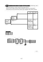
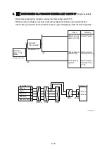
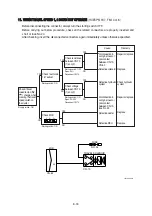
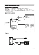
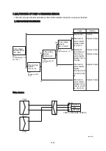
13. WHEN STARTING SWITCH ON DOES NOT OPERATE
13. WHEN STARTING SWITCH ON DOES NOT OPERATE
·
Before disconnecting the connector, always turn the starting switch OFF.
·
Before carrying out below procedure, check all the related connectors are properly inserted, master
switch ON and check open circuit of circuit breaker (CN-60, CN-95).
·
After checking, insert the disconnected connectors again immediately unless otherwise specified.
Cause
Remedy
Disconnection in
wiring harness or
defective battery
relay
Disconnection in
wiring harness or
poor contact
between CS-2A (2)-
CN-5(39)- CR-1
Defective start
switch
Disconnection in
wiring harness or
poor contact
between CS-2 (1)-
CN-5 (36)
Disconnection in
wiring harness or
poor contact
between CS-74B
(1) -CN-5 (36)
ⓐ
Battery capacity
too low
Defective master
switch
Disconnection in
wiring harness or
poor contact
between CS-74A
(2) -CR-1
Repair or replace
(after clean)
Repair or replace
(after clean)
Replace
Replace
Charge or replace
(after clean)
Charge or replace
(after clean)
Replace
Charge or replace
(after clean)
Specific gravity : MIN 1.28
Voltage : MIN 24V
Check voltage
and specific
gravity of battery
Voltage : 20~30V
Voltage : 20~30V
Starting switch : ON
Voltage : 20~30V
NO.19
NO.11
CN-231
1
2
CN-36-1
7
5
CN-36-3
1
9
NO.15
8
START MOTOR
1
2
16
17
CN-2
START RY
CR-23
ANTI-RESTART RY
CR-5
30
86
87
85
87a
86
85 87
30
87a
ANTI-RESTART RY
20
MCU
CN-51
BATT RY
CR-1
BATTERY
2
1
CN-60
2
1
CN-95
CIRCUIT BREAKER
MASTER SW
CS-74A
POWER RY
CR-35
40
39
36
CN-5
35
4
2
CN-125
START KEY SW
30
86
87
85
87a
86
85
87
30
87a
B+
M
M
CN-45
NO.2
NO.3
2
1
MASTER SW
CS-74B
2
1
60A
90A
69
KEY IG
CN93-J1
ECM
CS-2A
6
1
2
3
4
5
6
1
5
3
0
I
0,
I
H
4
2
B
H
BR
ACC
ST
C
Check voltage
between DO-3
(2) and chassis
Check voltage
between CS-2A
(2) and chassis
Check voltage
between CS-2A
(1) and chassis
YES
YES
YES
YES
NO
NO
NO
NO
145LCR6ES14
Voltage : 20~30V
Voltage : 20~30V
Check voltage
between
CS-74B (1) and
chassis
Check voltage
between CN-5
(36) and chassis
YES
YES
NO
NO
Voltage : 20~30V
NO
YES
ⓐ
Check voltage
between CS-
74A (2)- chassis
Содержание HX145 LCR
Страница 11: ...SECTION 1 GENERAL SECTION 1 GENERAL Group 1 Safety Hints 1 1 Group 2 Specifications 1 10...
Страница 204: ...4 5 MEMORANDUM HYUNDAI HEAVY INDUSTRIES CO LTD CONSTRUCTION EQUIPMENT DIV...
Страница 553: ...8 82 Insert O rings to the relief valve 30 and reassemble them to rear cover 20 This completes assembly 17 32038SM42...
Страница 627: ...8 155 125LCR8TM30 Turn casing 1 upside down and remove oil seal 3 using jig 29...
Страница 636: ...8 164 125LCR8TM61 After assembling spring 44 in order clamp plug 41 Tightening torque 5 kgf m 36 lbf ft 31...
Страница 657: ...8 185 8 185 Remove lock nut 22 and then boot 23 14 36078RL14 2507ARL10...
Страница 668: ...8 196 14 15 3 Install cover 3 to body 1 and tighten bolts 14 Torque 10 12 5 kgf m 72 3 90 4 lbf ft 7 21078DA10...


