8-208
DISASSEMBLY
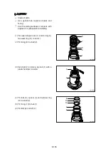
Remove cylinder head and piston rod
Procedures are based on the bucket
cylinder.
Hold the clevis section of the tube in a
vise.
Use mouth pieces so as not to damage
the machined surface of the cylinder
tube. Do not make use of the outside
piping as a locking means.
2
200mm
2
22
Hexagon
socket wrench
Cover here
with rag
Turn counter
clockwise
Full straight
sideways
Lift
Oil pan
(1)
3)
ö
Η
ö
Draw out cylinder head and rod assembly
together from tube assembly (1).
Since the rod assembly is heavy in this
case, lift the tip of the rod assembly (2)
with a crane or some means and draw it
out. However, when rod assembly (2)
has been drawn out to approximately
two thirds of its length, lift it in its center
to draw it completely.
Κ
ö
Loosen and remove socket bolts (22) of
the gland in sequence.
Cover the extracted rod assembly (2)
with rag to prevent it from being
accidentally damaged during operation.
Ι
ö
Pull out rod assembly (2) about
200mm (7.1in). Because the rod
a s s e m bl y i s ra t h e r h e av y, f i n i s h
extending it with air pressure after the oil
draining operation.
Θ
21078DA30
21078DA31
21078DA32
Содержание HX145 LCR
Страница 11: ...SECTION 1 GENERAL SECTION 1 GENERAL Group 1 Safety Hints 1 1 Group 2 Specifications 1 10...
Страница 204: ...4 5 MEMORANDUM HYUNDAI HEAVY INDUSTRIES CO LTD CONSTRUCTION EQUIPMENT DIV...
Страница 553: ...8 82 Insert O rings to the relief valve 30 and reassemble them to rear cover 20 This completes assembly 17 32038SM42...
Страница 627: ...8 155 125LCR8TM30 Turn casing 1 upside down and remove oil seal 3 using jig 29...
Страница 636: ...8 164 125LCR8TM61 After assembling spring 44 in order clamp plug 41 Tightening torque 5 kgf m 36 lbf ft 31...
Страница 657: ...8 185 8 185 Remove lock nut 22 and then boot 23 14 36078RL14 2507ARL10...
Страница 668: ...8 196 14 15 3 Install cover 3 to body 1 and tighten bolts 14 Torque 10 12 5 kgf m 72 3 90 4 lbf ft 7 21078DA10...


