


6-39
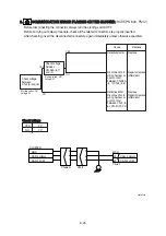
16. WHEN STARTING SWITCH IS TURNED ON, WORK LAMP DOES NOT LIGHTS UP
16. WHEN STARTING SWITCH IS TURNED ON, WORK LAMP DOES NOT LIGHTS UP
·
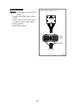
Before disconnecting the connector, always turn the starting switch OFF.
·
Before carrying out below procedure, check all the related connectors are properly inserted and
short of fuse No.17.
·
After checking, insert the disconnected connectors again immediately unless otherwise specified.
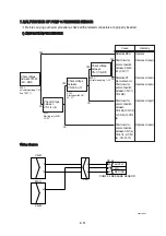
FUSE
NO.17
WORK LAMP
CL-6
2
1
CR-4
WORK LAMP RY
30
86
87
85
87a
30 86
85
87
87a
CL-5
2
1
CN-12
2
1
CN-376
MEMBRANE CONTROLLER
1
2
3
4
5
6
7
8
9
10
11
12
CAN_LO(2)
INT WIPER
NC
13
NC
14
OVERLOAD SW
15
16
17
18
TRVEL ALARM
19
26
27
CAN_HI(2)
GND
HEAD LIGHT
NC
GND
NC
WIPER
CABIN LIGHT
NC
WORK LIGHT
NC
NC
NC
BEACO LAMP SW
IG 24V
WASHER
34
Cause
Remedy
Defective bulb
Disconnection in
wiring harness or
poor contact
between CR-4
(87)-CL-5 (2)
Defective switch
panel
Disconnection in
wiring harness or
poor contact
between CR-4
(85)-CN-376 (4)
Disconnection in
wiring harness or
poor contact
between CR-4
(30) and chassis
or CR-4 (86) and
chassis
Recheck fuse
No.17
Replace
Repair or replace
(after clean)
Replace
Repair or replace
(after clean)
Repair or replace
(after clean)
Replace
Check voltage
between CR-4
(30) and chassis,
CR-4(86) chassis
YES
YES
Starting switch : ON
Voltage : 20~30V
Starting switch : ON
Work lamp switch : ON
Voltage : 20~30V
Starting switch : ON
Work lamp switch : ON
Voltage : 20~30V
Check voltage
between CN-376
(4) and chassis
Check voltage
between CR-4
(87) and chassis
NO
YES
NO
NO
140L6ES12
Check voltage
between CL-5 (1)
and chassis
YES
NO
Содержание HX145 LCR
Страница 11: ...SECTION 1 GENERAL SECTION 1 GENERAL Group 1 Safety Hints 1 1 Group 2 Specifications 1 10...
Страница 204: ...4 5 MEMORANDUM HYUNDAI HEAVY INDUSTRIES CO LTD CONSTRUCTION EQUIPMENT DIV...
Страница 553: ...8 82 Insert O rings to the relief valve 30 and reassemble them to rear cover 20 This completes assembly 17 32038SM42...
Страница 627: ...8 155 125LCR8TM30 Turn casing 1 upside down and remove oil seal 3 using jig 29...
Страница 636: ...8 164 125LCR8TM61 After assembling spring 44 in order clamp plug 41 Tightening torque 5 kgf m 36 lbf ft 31...
Страница 657: ...8 185 8 185 Remove lock nut 22 and then boot 23 14 36078RL14 2507ARL10...
Страница 668: ...8 196 14 15 3 Install cover 3 to body 1 and tighten bolts 14 Torque 10 12 5 kgf m 72 3 90 4 lbf ft 7 21078DA10...