GE Analytical Instruments ©2010
90 of 226
DLM 74001-04 Rev. A
Chapter 4: Basic Analyzer Operation
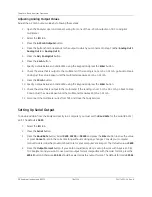
Adjusting Display Contrast Settings
The Analyzer’s color LCD can be adjusted for proper viewing in your environment as follows:
1. Select the
Maintenance
tab.
2. Press the
Advanced
button.
3. Press the
Advanced Setup
button.
4. Press the
Contrast Adjust
button and use the keypad to change the contrast level of the display. Press
Enter
to change the contrast to the new value, and then push
Menu
to exit. Use a smaller number to
increase screen brightness.
Naming the Analyzer Location
You can assign a name to the Analyzer that displays on printed and exported data. This feature is particularly
useful if you have multiple Analyzers at your facility and want to easily distinguish data collected from each
instrument. To assign a name, follow these steps:
1. Select the
Maintenance
tab.
2. Press the
Advanced
button.
3. Press the
Advanced
Setup
button.
4. Press the
Location
button.
5. Use the keypad to specify a name for the Analyzer and press
Enter
.
Changing the Display Mode
By default, the Analyzer displays the TOC and conductivity values on the
Main
screen. You can change the
display for other values as follows:
1. Select the
Maintenance
tab.
2. Press the
Advanced
button.
3. Press the
Advanced
Setup
button.
4. Press the
Display Mode
button.
5. Select the values you want displayed on the Main screen:
TOC/tCond
,
TOC/rCond/Temp
,
TOC
, or
TOC/
IC/TC
,
TOC/IC/rCond
,
TOC/IC/tCond
.
NOTE:
Your
Contrast Adjust
button may be inactive depending on the type of display in
your instrument. This display type does not need contrast adjustment.
Содержание Sievers 500 RL
Страница 8: ...GE Analytical Instruments 2010 8 of 226 DLM 74001 04 Rev A ...
Страница 10: ...GE Analytical Instruments 2010 10 of 226 DLM 74001 04 Rev A ...
Страница 36: ...GE Analytical Instruments 2010 36 of 220 DLM 74001 04 Rev A ...
Страница 66: ...GE Analytical Instruments 2010 66 of 226 DLM 74001 04 Rev A Chapter 3 Installation ...
Страница 152: ...GE Analytical Instruments 2010 152 of 226 DLM 74001 04 Rev A Chapter 7 Maintenance ...
Страница 170: ...GE Analytical Instruments 2010 170 of 226 DLM 74001 04 Rev A Chapter 8 Troubleshooting ...
Страница 177: ...Appendix A GE Analytical Instruments 2010 177 of 186 DLM 74001 04 Rev A Figure 51 Left Side Analyzer Dimensions ...
Страница 178: ...Appendix A GE Analytical Instruments 2010 178 of 186 DLM 74001 04 Rev A ...
Страница 185: ...Notes GE Analytical Instruments 2010 185 of 186 DLM 74001 04 Rev A 186 ...
Страница 186: ...Notes GE Analytical Instruments 2010 186 of 186 DLM 74001 04 Rev A 186 ...


