


GE Analytical Instruments ©2010
43 of 226
DLM 74001-04 Rev. A
Chapter 2: System Description
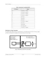
of the
iOS
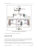
System or the Sample Inlet Block. The stream splitter divides the sample stream into two equal but
separate flows. One stream is processed for the measurement of IC; the other is processed for measurement of
TC.
The TC stream passes to an oxidation reactor where the sample is exposed to UV light, which oxidizes the
organic compounds in the sample, converting them to CO
2
. The reactor is a spiral quartz tube wrapped around
the UV lamp. The UV lamp emits light at 185 and 254 nm resulting in the formation of powerful chemical
oxidizing agent in the form of hydroxyl radicals produced by the photolysis of water (eq. 1):
H
2
O + h
(185 nm)
OH· + H·
(1)
The hydroxyl radicals (OH·) will completely oxidize organic compounds, converting the carbon atoms of the
organic compound into CO
2
.
Organic Com OH·
CO
2
+ H
2
O
(2)
The IC stream passes through a delay coil, which is designed to make the total transit time of the IC stream
through the Analyzer the same as the transit time of the TC stream through the Analyzer.
When the TC stream exits the oxidation reactor and the IC stream exits the delay coil, each stream moves to the
CO
2
transfer manifold. The CO
2
transfer manifold is a patented design, utilizing a gas-permeable membrane
that allows the transfer of CO
2
across the membrane. The membrane separates the sample side of the Analyzer
from the DI side. The DI side of the Analyzer is a closed loop, and consists of two conductivity cells—one for the
TC stream and one for the IC stream—a DI water pump, DI water reservoir, and ion exchange resin (resin bed).
CO
2
from the sample passes through the membrane into the DI water supplied by the integrated DI Loop, while
interfering compounds and other oxidation by-products are blocked by the membrane and remain on the
sample side. The CO
2
forms carbonic acid upon reaction with water, and the carbonic acid disassociates into
hydrogen ions and bicarbonate ions:
CO
2
+ H
2
O
H
2
CO
3
H
+
+ HCO
3
-
(3)
DI water is continuously pumped through the DI side of the Analyzer, collecting the H
+
and HCO
3
-
ions and
H
2
CO
3
and CO
2
molecules from the CO
2
transfer modules, delivering it to the conductivity cell for measurement.
Then the ion exchange resin removes the HCO
3
-
and H
+
. The water is then pumped back to the CO
2
transfer
module to repeat the sequence.
The TC and IC conductivity cells each contain a thermistor, and all conductivity readings are temperature
corrected. The CO
2
from the TC and IC sample streams are measured by the respective conductivity cells, and
the conductivity readings are used to calculate the concentration of TC and IC. Once the values are measured,
TOC is calculated as the difference:
TOC = TC - IC
(4)
Содержание Sievers 500 RL
Страница 8: ...GE Analytical Instruments 2010 8 of 226 DLM 74001 04 Rev A ...
Страница 10: ...GE Analytical Instruments 2010 10 of 226 DLM 74001 04 Rev A ...
Страница 36: ...GE Analytical Instruments 2010 36 of 220 DLM 74001 04 Rev A ...
Страница 66: ...GE Analytical Instruments 2010 66 of 226 DLM 74001 04 Rev A Chapter 3 Installation ...
Страница 152: ...GE Analytical Instruments 2010 152 of 226 DLM 74001 04 Rev A Chapter 7 Maintenance ...
Страница 170: ...GE Analytical Instruments 2010 170 of 226 DLM 74001 04 Rev A Chapter 8 Troubleshooting ...
Страница 177: ...Appendix A GE Analytical Instruments 2010 177 of 186 DLM 74001 04 Rev A Figure 51 Left Side Analyzer Dimensions ...
Страница 178: ...Appendix A GE Analytical Instruments 2010 178 of 186 DLM 74001 04 Rev A ...
Страница 185: ...Notes GE Analytical Instruments 2010 185 of 186 DLM 74001 04 Rev A 186 ...
Страница 186: ...Notes GE Analytical Instruments 2010 186 of 186 DLM 74001 04 Rev A 186 ...