


GE Analytical Instruments ©2010
164 of 226
DLM 74001-04 Rev. A
Chapter 8: Troubleshooting
5. When the calibration is complete, a summary screen will display:
Figure 43: The Sample Cell Calibration Results Screen
6. Press the
button to print the results. Press the
Apply
button to applies the calibration results or
press the
Cancel
button to exit without changing the sample conductivity cell values.
Sample Cell Zero
If for any reason the sample conductivity cell has been replaced, or you suspect poor performance of the cell,
you may need to perform a sample conductivity cell conductivity autozero. If you have also performed a sample
conductivity cell calibration, be sure to wait 5 hours after the calibration before performing the sample cell zero.
1. Make sure the Analyzer is not taking measurements.
2. Press the
Menu
button and select the
Maintenance
tab.
3. Press the
Cal/Ver/Validate
button.
4. Press the
Sample Cell Zero
button.
5. Follow the prompts on the screen.
TOC Autozero
The TOC Autozero corrects for minor differences in the response of the two CO
2
sensors. This adjustment may
help when the Analyzer is reading very high or negative values. If you have recently run a system protocol, let
the Analyzer run in On-Line mode for 30 minutes before performing a TOC Autozero.
The TOC Autozero requires that the on-line water supply be available to the Analyzer. Make sure the sample inlet
is configured properly before continuing.
1. If the Analyzer is taking measurements, press the
Stop Analysis
button.
2. Press the
Menu
button, select the
Maintenance
tab and press the
Cal/Ver/Validate
button.
3. Press
Run TOC Autozero
.
Содержание Sievers 500 RL
Страница 8: ...GE Analytical Instruments 2010 8 of 226 DLM 74001 04 Rev A ...
Страница 10: ...GE Analytical Instruments 2010 10 of 226 DLM 74001 04 Rev A ...
Страница 36: ...GE Analytical Instruments 2010 36 of 220 DLM 74001 04 Rev A ...
Страница 66: ...GE Analytical Instruments 2010 66 of 226 DLM 74001 04 Rev A Chapter 3 Installation ...
Страница 152: ...GE Analytical Instruments 2010 152 of 226 DLM 74001 04 Rev A Chapter 7 Maintenance ...
Страница 170: ...GE Analytical Instruments 2010 170 of 226 DLM 74001 04 Rev A Chapter 8 Troubleshooting ...
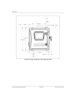
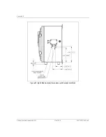
Страница 177: ...Appendix A GE Analytical Instruments 2010 177 of 186 DLM 74001 04 Rev A Figure 51 Left Side Analyzer Dimensions ...
Страница 178: ...Appendix A GE Analytical Instruments 2010 178 of 186 DLM 74001 04 Rev A ...
Страница 185: ...Notes GE Analytical Instruments 2010 185 of 186 DLM 74001 04 Rev A 186 ...
Страница 186: ...Notes GE Analytical Instruments 2010 186 of 186 DLM 74001 04 Rev A 186 ...