


GE Analytical Instruments ©2010
144 of 226
DLM 74001-04 Rev. A
Chapter 7: Maintenance
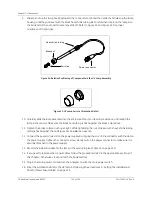
17. After changing the UV lamp, perform a calibration verification (see “Accuracy, Precision, and Calibration
Verification” on page 124).
Replacing the Sample Pump Tubing and Pump Heads
The tubing for the sample pump loses elasticity over time and must be replaced annually to ensure proper flow
rates; the tubing cannot be replaced independently of the sample pump heads, and is provided as a kit with new
pump heads. The sample pump tubing and pump heads must be purchased from GE Analytical Instruments; use
of tubing from other sources or failure to replace the tubing on the prescribed replacement schedule will affect
Analyzer functionality.
Have paper towels available during the procedure in case water leaks from the old pump heads during the
removal process. Reference Figure 36 on page 145, as needed.
1. If the Analyzer is taking measurements, press the
Stop Analysis
button.
2. Turn off the Analyzer by using the main power switch.
3. Stop the flow of sample water to the Analyzer.
4. Open the Analyzer front panel.
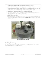
5. Locate the sample pump heads (see Figure 32 on page 140).
6. Remove the masterflex tubing from the four barbs.
7. Use a small Phillips screwdriver (from the accessories kit) to loosen the two screws that secure the
pump heads. Remove the screws and retain them.
8. Pull both pump heads straight out and off the shaft. Dispose of the old pump heads. Use a paper towel
to clean any dripping that occurs.
9. Remove the new pump heads from the packaging. Slide one pump head onto the shaft and push it all
the way back, making sure the set pins are seated properly. You may need to “walk” the pump head
onto the shaft. The shaft is a “D” and must align properly with the pump heads.
10. Repeat Step 9 for the second pump head.
11. Replace and secure the two Phillips screws.
Warning
Installation of the sample pump tubing and pump heads requires
access to the inside of the Analyzer. To avoid potentially dangerous
shock, disconnect the power cord before opening the Analyzer’s front
panel.
Содержание Sievers 500 RL
Страница 8: ...GE Analytical Instruments 2010 8 of 226 DLM 74001 04 Rev A ...
Страница 10: ...GE Analytical Instruments 2010 10 of 226 DLM 74001 04 Rev A ...
Страница 36: ...GE Analytical Instruments 2010 36 of 220 DLM 74001 04 Rev A ...
Страница 66: ...GE Analytical Instruments 2010 66 of 226 DLM 74001 04 Rev A Chapter 3 Installation ...
Страница 152: ...GE Analytical Instruments 2010 152 of 226 DLM 74001 04 Rev A Chapter 7 Maintenance ...
Страница 170: ...GE Analytical Instruments 2010 170 of 226 DLM 74001 04 Rev A Chapter 8 Troubleshooting ...
Страница 177: ...Appendix A GE Analytical Instruments 2010 177 of 186 DLM 74001 04 Rev A Figure 51 Left Side Analyzer Dimensions ...
Страница 178: ...Appendix A GE Analytical Instruments 2010 178 of 186 DLM 74001 04 Rev A ...
Страница 185: ...Notes GE Analytical Instruments 2010 185 of 186 DLM 74001 04 Rev A 186 ...
Страница 186: ...Notes GE Analytical Instruments 2010 186 of 186 DLM 74001 04 Rev A 186 ...