


GE Analytical Instruments ©2010
82 of 226
DLM 74001-04 Rev. A
Chapter 4: Basic Analyzer Operation
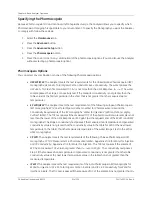
•
TOC Limit
— The alarm is triggered when the TOC level exceeds the TOC value (in PPB) as
determined by the last system suitability verification.
•
Cond Limit
— The alarm is triggered when the conductivity level exceeds the limit specified for
the sample’s temperature in the currently selected pharmacopeia.
•
Meas. Done
— The alarm is triggered for 2 seconds when the Analyzer finishes a measurement
cycle and returns a reading.
•
Limits
— The alarm is triggered when measurements exceed the TOC limit or the conductivity
limit.
•
Break In
— The alarm is triggered after five unsuccessful log in attempts by a single User ID. See
“Reactivating Inactivated User Accounts” on page 109 for more information.
5. Press the
Menu
button when you are done.
While the Analyzer is running system protocols, such as calibration, only the alarms for
Error/Warning
,
Power Fail
, and
Break In
are in an active monitoring state.
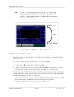
Using the Ethernet Connection and Modbus
When exporting data to the Ethernet port, the Analyzer uses the Modbus communication protocol (port 502).
Before data can be exported via Ethernet, you must enable Modbus and configure the Analyzer's IP address
(refer to Figure 16 on page 83). The connection can be made using DHCP or a static IP address.
1. Select the
I/O
tab.
2. Press the
Modbus
button.
• Press the
Modbus
button and select
Enabled
.
• Press the
Method
button and select either
DHCP
or
Fixed
. If you select
Fixed
, press the
IP Address
and
IP Mask
buttons and enter the appropriate addresses.
3. Press the
Back
button.
Note:
You may need assistance from your network administrator or information technology
(IT) department to set the IP address correctly for your network
Содержание Sievers 500 RL
Страница 8: ...GE Analytical Instruments 2010 8 of 226 DLM 74001 04 Rev A ...
Страница 10: ...GE Analytical Instruments 2010 10 of 226 DLM 74001 04 Rev A ...
Страница 36: ...GE Analytical Instruments 2010 36 of 220 DLM 74001 04 Rev A ...
Страница 66: ...GE Analytical Instruments 2010 66 of 226 DLM 74001 04 Rev A Chapter 3 Installation ...
Страница 152: ...GE Analytical Instruments 2010 152 of 226 DLM 74001 04 Rev A Chapter 7 Maintenance ...
Страница 170: ...GE Analytical Instruments 2010 170 of 226 DLM 74001 04 Rev A Chapter 8 Troubleshooting ...
Страница 177: ...Appendix A GE Analytical Instruments 2010 177 of 186 DLM 74001 04 Rev A Figure 51 Left Side Analyzer Dimensions ...
Страница 178: ...Appendix A GE Analytical Instruments 2010 178 of 186 DLM 74001 04 Rev A ...
Страница 185: ...Notes GE Analytical Instruments 2010 185 of 186 DLM 74001 04 Rev A 186 ...
Страница 186: ...Notes GE Analytical Instruments 2010 186 of 186 DLM 74001 04 Rev A 186 ...