


GE Analytical Instruments ©2010
51 of 226
DLM 74001-04 Rev. A
Chapter 3: Installation
Wiring the 4-20 mA Connection
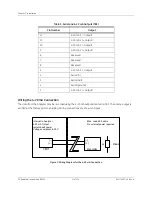
The data from the Analyzer may be recorded using the 4-20 mA outputs located on TB3. The analog output is
verified at the factory prior to shipping. Wiring connections are shown in Figure .
Figure 3: Wiring Diagram for the 4-20 mA Connection
Table 3: Serial and 4-20 mA Outputs (TB3)
Pin Number
Output
12
4-20 mA 1 (- Output)
11
4-20 mA 1 (+ Output)
10
4-20 mA 2 (- Output)
9
4-20 mA 2 (+ Output)
8
Reserved
7
Reserved
6
Reserved
5
4-20 mA 3 (- Output)
4
Serial (In)
3
Serial (Out)
2
Serial (ground)
1
4-20 mA 3 (+ Output)
(-)
(+)
TB3
Internal to Analyzer
4-20 mA Output
Isolated self power
Voltage compliant to 20 V
Max. Load 600 ohms
No external power required
(-)
(+)
Recorder
or
Rload
Содержание Sievers 500 RL
Страница 8: ...GE Analytical Instruments 2010 8 of 226 DLM 74001 04 Rev A ...
Страница 10: ...GE Analytical Instruments 2010 10 of 226 DLM 74001 04 Rev A ...
Страница 36: ...GE Analytical Instruments 2010 36 of 220 DLM 74001 04 Rev A ...
Страница 66: ...GE Analytical Instruments 2010 66 of 226 DLM 74001 04 Rev A Chapter 3 Installation ...
Страница 152: ...GE Analytical Instruments 2010 152 of 226 DLM 74001 04 Rev A Chapter 7 Maintenance ...
Страница 170: ...GE Analytical Instruments 2010 170 of 226 DLM 74001 04 Rev A Chapter 8 Troubleshooting ...
Страница 177: ...Appendix A GE Analytical Instruments 2010 177 of 186 DLM 74001 04 Rev A Figure 51 Left Side Analyzer Dimensions ...
Страница 178: ...Appendix A GE Analytical Instruments 2010 178 of 186 DLM 74001 04 Rev A ...
Страница 185: ...Notes GE Analytical Instruments 2010 185 of 186 DLM 74001 04 Rev A 186 ...
Страница 186: ...Notes GE Analytical Instruments 2010 186 of 186 DLM 74001 04 Rev A 186 ...