


GE Analytical Instruments ©2010
77 of 226
DLM 74001-04 Rev. A
Chapter 4: Basic Analyzer Operation
Setting Up Analog Output
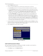
The Sievers 500 RL On-Line TOC Analyzer has three 4-20 mA outputs. Select the output range for the 4-20 mA
analog outputs by following the steps below. Instructions for wiring the 4-20mA output can be found in the
“Installation” chapter on page 51. On configurations without conductivity measurement, some options are not
available.
1. Select the
I/O
tab.
2. Press the
4-20mA Outputs
button.
3. Press the
Error/Standby Configuration
button. The settings here are applied to all the analog outputs
when each condition exists.
• Press the
Error
button and then press a button on the right to indicate the value for an error
condition, either
1 mA
,
2.5 mA
,
4 mA
,
20 mA
,
22mA
, or
LAST
. (
LAST
= Hold the last measurement
until the next measurement.) The initial default value is
2.5 mA
.
• Press the
Standby
button and then press a button on the right to indicate the value when the
Analyzer switches out of Analysis mode and into Standby mode, either
1 mA
,
2.5 mA
,
4 mA
,
20 mA
,
22 mA
or
LAST.
The initial default value is
1 mA
.
• Press the
Warning
button and then press a button on the right to indicate the value for a warning
condition, either
1 mA
,
2.5 mA
,
4 mA
,
20 mA
,
22 mA
, or
LAST
.
The initial default value is
LAST
.
4. Press the
Back
button.
5. Press one of the Analog Out buttons, either
Analog Out 1
,
Analog Out 2
, or
Analog Out 3
. Set the
values for the following:
• Press the
Value
button to set the output value that will be sent to the analog output. Press the
TOC
,
TC
,
IC
,
rCond
,
tCond
, or
Temp
button and then press
Enter
to change the value, or press
Cancel
to
retain the current setting without making any changes.
• Press the
Min
button to set the minimum value (in ppb or µS), corresponding to the minimum analog
current. Enter a number and press the
Enter
button to save the value, or press
Cancel
to retain the
current setting without making any changes.
• Press the
Max
button to set the maximum value (in ppb or µS), corresponding to the maximum
analog current. Enter a number and press the
Enter
button to save the value, or press
Cancel
to
retain the current setting without making any changes.
6. To adjust the values output via the 4-20 mA outputs, see “Adjusting Analog Output Values” below.
Note:
The values for
Error
,
Standby
, and
Warning
should be different.
Содержание Sievers 500 RL
Страница 8: ...GE Analytical Instruments 2010 8 of 226 DLM 74001 04 Rev A ...
Страница 10: ...GE Analytical Instruments 2010 10 of 226 DLM 74001 04 Rev A ...
Страница 36: ...GE Analytical Instruments 2010 36 of 220 DLM 74001 04 Rev A ...
Страница 66: ...GE Analytical Instruments 2010 66 of 226 DLM 74001 04 Rev A Chapter 3 Installation ...
Страница 152: ...GE Analytical Instruments 2010 152 of 226 DLM 74001 04 Rev A Chapter 7 Maintenance ...
Страница 170: ...GE Analytical Instruments 2010 170 of 226 DLM 74001 04 Rev A Chapter 8 Troubleshooting ...
Страница 177: ...Appendix A GE Analytical Instruments 2010 177 of 186 DLM 74001 04 Rev A Figure 51 Left Side Analyzer Dimensions ...
Страница 178: ...Appendix A GE Analytical Instruments 2010 178 of 186 DLM 74001 04 Rev A ...
Страница 185: ...Notes GE Analytical Instruments 2010 185 of 186 DLM 74001 04 Rev A 186 ...
Страница 186: ...Notes GE Analytical Instruments 2010 186 of 186 DLM 74001 04 Rev A 186 ...