


GE Analytical Instruments ©2010
74 of 226
DLM 74001-04 Rev. A
Chapter 4: Basic Analyzer Operation
Graphing Data History
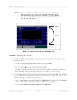
You can set the time scale for the data that is displayed on the graph and specify which data are displayed. The
settings you specify on the
Graph
screen also affect the graph that is displayed on the
Main
screen. On
configurations without conductivity measurement, some options are not available.
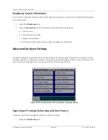
To customize the graph, follow these steps:
1. Select the
Data
tab.
2. Press the
Graph
button to display the data graph (see Figure 14).
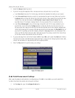
3. Press the
Setup
button to specify the scale for the graph.
4. Press the
Type
button to specify which data are displayed on the graph:
TOC
only,
TOC/IC/TC
,
Sample
Cond.
, or
Sample Temp.
5. Press the
X Scale
button and select a time range for the X axis of the graph:
1 Hour
,
2 Hour
,
4 Hour
,
8
Hour
,
1 Day
,
2 Days
,
1 Week
.
6. Press the
Y Scale
button to select a range for the Y axis.
• Select
Auto
to have the Analyzer automatically calculate the appropriate range.
• Select
Manual
to enter specific TOC values in ppb or conductivity values in µS. Press the
Min
button
to enter the minimum value and press the
Max
button to enter the maximum value.
7. Press the
Back
button to save your changes and return to the graph display. A color-coded key displays
to help identify the graph lines for each type of data.
8. To begin the graph from a specific measurement, press the
Go To
button, enter the appropriate date or
time values, press
Enter
, and press the
Back
button.
Note:
Settings specified in the
Setup
screen affect the display of the graph on the
Main
screen, in addition to the graph displayed under the
Data
tab.
Содержание Sievers 500 RL
Страница 8: ...GE Analytical Instruments 2010 8 of 226 DLM 74001 04 Rev A ...
Страница 10: ...GE Analytical Instruments 2010 10 of 226 DLM 74001 04 Rev A ...
Страница 36: ...GE Analytical Instruments 2010 36 of 220 DLM 74001 04 Rev A ...
Страница 66: ...GE Analytical Instruments 2010 66 of 226 DLM 74001 04 Rev A Chapter 3 Installation ...
Страница 152: ...GE Analytical Instruments 2010 152 of 226 DLM 74001 04 Rev A Chapter 7 Maintenance ...
Страница 170: ...GE Analytical Instruments 2010 170 of 226 DLM 74001 04 Rev A Chapter 8 Troubleshooting ...
Страница 177: ...Appendix A GE Analytical Instruments 2010 177 of 186 DLM 74001 04 Rev A Figure 51 Left Side Analyzer Dimensions ...
Страница 178: ...Appendix A GE Analytical Instruments 2010 178 of 186 DLM 74001 04 Rev A ...
Страница 185: ...Notes GE Analytical Instruments 2010 185 of 186 DLM 74001 04 Rev A 186 ...
Страница 186: ...Notes GE Analytical Instruments 2010 186 of 186 DLM 74001 04 Rev A 186 ...