


GE Analytical Instruments ©2010
44 of 226
DLM 74001-04 Rev. A
Chapter 2: System Description
Additional System Components
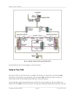
Microprocessor Controller and Electronics
Six proprietary electronic board assemblies monitor and control Analyzer functions:
•
System board
including the 32-bit microprocessor, 1 MB of program memory, 1 MB of data memory,
battery-backed nonvolatile memory for operator settings, digital I/O, QVGA color graphics controller,
stepper motor controllers, printer output, RS-232 (serial) port, interface to USB storage devices, and the
Ethernet port.
•
Analog-to-digital conversion board
with integrated signal conditioning circuits for three conductivity
and four temperature measurements
•
Color LCD QVGA display
with touch panel
•
Passive interconnect board
•
ID board
with nonvolatile memory for system specific coefficients
•
I/O board
with interfaces to external devices, via binary input, four alarms, and three 4-20 mA outputs
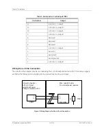
Data Outputs
The Analyzer has serial (RS-232), USB, and printer ports, allowing flexibility for exporting and printing data. Real-
time and historical data can be transferred from the Analyzer via the serial port to a computer using
communication software such as HyperTerminal (for details, see “Using HyperTerminal” on page 179). Historical
data can be transferred from the Analyzer via the USB port to a USB flash storage device (provided) and then
transferred to any computer that supports USB. The Sievers 500 RL On-Line TOC Analyzer also has three analog
outputs (4-20 mA) which can be customized to track specific data values, four alarms, and two binary ports.
Note:
The Analyzer cannot be directly connected to a computer via the USB port. Rather, the
Analyzer’s USB port can only be connected to a USB storage device, such as a USB flash
memory drive.
Содержание Sievers 500 RL
Страница 8: ...GE Analytical Instruments 2010 8 of 226 DLM 74001 04 Rev A ...
Страница 10: ...GE Analytical Instruments 2010 10 of 226 DLM 74001 04 Rev A ...
Страница 36: ...GE Analytical Instruments 2010 36 of 220 DLM 74001 04 Rev A ...
Страница 66: ...GE Analytical Instruments 2010 66 of 226 DLM 74001 04 Rev A Chapter 3 Installation ...
Страница 152: ...GE Analytical Instruments 2010 152 of 226 DLM 74001 04 Rev A Chapter 7 Maintenance ...
Страница 170: ...GE Analytical Instruments 2010 170 of 226 DLM 74001 04 Rev A Chapter 8 Troubleshooting ...
Страница 177: ...Appendix A GE Analytical Instruments 2010 177 of 186 DLM 74001 04 Rev A Figure 51 Left Side Analyzer Dimensions ...
Страница 178: ...Appendix A GE Analytical Instruments 2010 178 of 186 DLM 74001 04 Rev A ...
Страница 185: ...Notes GE Analytical Instruments 2010 185 of 186 DLM 74001 04 Rev A 186 ...
Страница 186: ...Notes GE Analytical Instruments 2010 186 of 186 DLM 74001 04 Rev A 186 ...