


GE Analytical Instruments ©2010
162 of 226
DLM 74001-04 Rev. A
Chapter 8: Troubleshooting
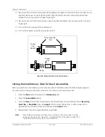
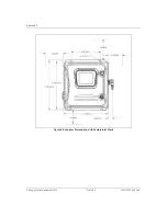
Figure 41: The Inlet and Outlet Connections Inside the Analyzer
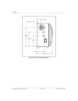
9. Swap the two pairs of connections leading to the sample pump tubing at the plastic barbs (see
Figure 42). The first pair of tubes (on the left) should be connected to the barbs that normally connect to
the second pair of tubes (on the right). The second pair of tubes (on the right) should be connected to
the barbs that normally connect to the first pair of tubes (on the left).
Figure 42: The Sample Pump Tubing Connections
Содержание Sievers 500 RL
Страница 8: ...GE Analytical Instruments 2010 8 of 226 DLM 74001 04 Rev A ...
Страница 10: ...GE Analytical Instruments 2010 10 of 226 DLM 74001 04 Rev A ...
Страница 36: ...GE Analytical Instruments 2010 36 of 220 DLM 74001 04 Rev A ...
Страница 66: ...GE Analytical Instruments 2010 66 of 226 DLM 74001 04 Rev A Chapter 3 Installation ...
Страница 152: ...GE Analytical Instruments 2010 152 of 226 DLM 74001 04 Rev A Chapter 7 Maintenance ...
Страница 170: ...GE Analytical Instruments 2010 170 of 226 DLM 74001 04 Rev A Chapter 8 Troubleshooting ...
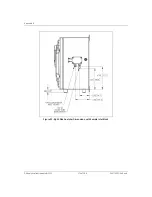
Страница 177: ...Appendix A GE Analytical Instruments 2010 177 of 186 DLM 74001 04 Rev A Figure 51 Left Side Analyzer Dimensions ...
Страница 178: ...Appendix A GE Analytical Instruments 2010 178 of 186 DLM 74001 04 Rev A ...
Страница 185: ...Notes GE Analytical Instruments 2010 185 of 186 DLM 74001 04 Rev A 186 ...
Страница 186: ...Notes GE Analytical Instruments 2010 186 of 186 DLM 74001 04 Rev A 186 ...