GE Analytical Instruments ©2010
122 of 226
DLM 74001-04 Rev. A
Chapter 6: Calibration and System Protocols
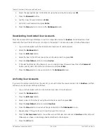
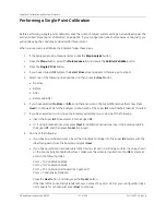
14. The Analyzer indicates if the calibration passed.
• If the calibration passed, press the
Apply
button to accept the calibration and continue.
• If the calibration failed, press the
Cancel
button to reject the calibration. You may need to perform
the calibration procedure again. However, first consult the chapter called “Troubleshooting” on
page 153 to determine if there is a problem with the Analyzer.
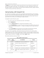
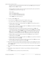
The summary screens show data collected for each of the vials, as well as several calculated values.
Exp
is expected value. For
RW IC
(TOC Calibration Blank), this is the measured value for the TC channel,
with the UV lamp off. For
1.50ppm TOC
(TOC Calibration Standard), this is the expected value for
RW2
TOC
plus 1.5 ppm. For
1.00ppm TOC
and
500 ppb TOC
(TOC Calibration Standards), this is the expected
value for RW3 plus 1.00 ppm or 500 ppb, respectively. For
25.00 S/cm tCond
(Conductivity Standard),
this is the certified value of the standard, as shown on the vial label.
Diff
is percent difference between the average and expected value.
Adj
is the adjusted value, with the new calibration applied.
15. Press
Exit
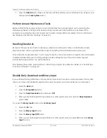
.
16. If you have a Super
iOS
system, and selected the
After
or the
Before and After
option, the Analyzer will
prompt you to remove the standards, and to insert the rinse cartridge or vials into the Super
iOS
system
to continue the Rinse activity. Take out the rinse cartridge or vials when completed.
17. If you have a standard
iOS
System, remove the standards and slide the
iOS
door closed.
18. You should now verify the calibration. Proceed to “Accuracy, Precision, and Calibration Verification” on
page 124 for instructions.
Figure 26: The First Summary Screen in a Multi-Point Calibration
Содержание Sievers 500 RL
Страница 8: ...GE Analytical Instruments 2010 8 of 226 DLM 74001 04 Rev A ...
Страница 10: ...GE Analytical Instruments 2010 10 of 226 DLM 74001 04 Rev A ...
Страница 36: ...GE Analytical Instruments 2010 36 of 220 DLM 74001 04 Rev A ...
Страница 66: ...GE Analytical Instruments 2010 66 of 226 DLM 74001 04 Rev A Chapter 3 Installation ...
Страница 152: ...GE Analytical Instruments 2010 152 of 226 DLM 74001 04 Rev A Chapter 7 Maintenance ...
Страница 170: ...GE Analytical Instruments 2010 170 of 226 DLM 74001 04 Rev A Chapter 8 Troubleshooting ...
Страница 177: ...Appendix A GE Analytical Instruments 2010 177 of 186 DLM 74001 04 Rev A Figure 51 Left Side Analyzer Dimensions ...
Страница 178: ...Appendix A GE Analytical Instruments 2010 178 of 186 DLM 74001 04 Rev A ...
Страница 185: ...Notes GE Analytical Instruments 2010 185 of 186 DLM 74001 04 Rev A 186 ...
Страница 186: ...Notes GE Analytical Instruments 2010 186 of 186 DLM 74001 04 Rev A 186 ...


